


Factory Service Manual For Bomag Sanitary Landfill And Fast Moving Soil Compactor. Manual Contains Illustrations, Instructions, Diagrams For Step By Step Remove And Install, Assembly And Disassembly, Service, Inspection, Repair, Troubleshooting, Tune-Ups.
Format: PDF
Language: ENG
Pages: 1022
Number: 00891153 (october 2010)
Bookmarks: Yes
Searchable: Yes
Wiring Diagrams: Yes
Hydraulic Diagrams: Yes
Model
Bomag Sanitary Landfill Compactor And Fast Moving Soil Compactor
BC672RB-2
BC772RB-2
BC772RS-2
BC672EB-2
BC772EB-2
S/N 10157059 ….
S/N 10157058 ….
S/N 10157057 ….
S/N 10157093 ….
S/N 10157092 ….
Contents
-GENERAL
Introduction
Safety Regulations
General Repair Instructions
Tightening Torques
-TECHNICAL DATA
Technical Data
-MAINTENANCE
General Notes On Maintenance
Fuels And Lubricants
Table Of Fuels And Lubricants
Running-In Instructions
Maintenance Table
-ELECTRICS
Understanding Circuit Diagrams
Designation Of Components In The Wiring Diagram
Terminal Designations In Wiring Diagram
Circuit Symbols In The Circuit Diagram
Battery Ground And Analog Ground
Current And Voltage
Resistance
Series / Parallel Connection
Ohm’s Law
Electrical Energy
Formula Diagram
Metrology
Diodes, Relays, Fuses
Telemechanique Switch
Plug Connectors
Magnetic Coil Plug
Deutsch Plug, Series DT And DTM
Plugs And Terminals In Spring Clamping Technology
Batteries
Battery Service, Check The Main Battery Switch
Starting The Engine With Jump Leads
Main Battery Switch
Main Fuse
Hydraulic Oil Temperature
Pressure Switch, Hydraulic Oil Filter
Magnetic Sensor, Hydraulic Oil
Pressure Switch For Brake
Level Sensor In Diesel Tank (R03)
Blower Monitoring Module A53
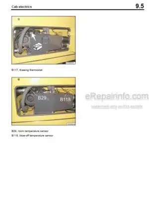
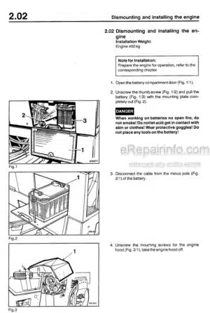
Cab Electrics
Fuses
Fuse, Cabin
Machine Related Electrics
Electronic Control Units
Checking The Voltage Supply For The Control Unit
Diagnostics Concept
-ENGINE ELECTRICS
Engine Control Unit
Pin Assignment
System Faults Indicated By Flashing Code
Flashing Code
Diagnose With Serdia
Diagnose With Can-Bus
Diagnostics Interface
Emr3 List Of Fault Codes
Sensors
Oil Pressure Sensor
Fuel Temperature Sensor
Charge Air Temperature – Charge Air Pressure Sensor
EMR Coolant Temperature Sensor
Rotary Speed Sensor For Crankshaft
Rotary Speed Sensor For Camshaft
Preheating System
Checking The Preheating System. Maintenance In Case Of Frost.
Sensor, Water In Fuel
Air Filter Vacuum Switch
Coolant Temperature Sensor
Float Switch, Coolant Tank
Charge Control Light, Engine Rpm-Meter
Generator
Replacing The Voltage Regulator
Electric Starter
-ELECTRONIC CONTROL
ESX Control
-TROUBLE SHOOTING
Notes On Trouble Shooting
The Machine Drives With The Travel Lever In „Neutral“
The Machine Does Not Drive
Machine Travels To One Direction Only Or To One Travel Direction With Reduced Power
Hydraulic Oil Overheating
Insufficient Travel Power, Max Speed Is Not Reached
No Steering Function / Steering Stiff, End Stops Are Not Reached
Failure Of Central Lubrication System (Grease Emerges From Relief Valve)
Trouble Shooting Travel System
Trouble Shooting Working Hydraulics
-INSTALLED COMPONENTS / CONNECTION OVERVIEW
List Of Installed Components
Measuring And Adjustment Points On Tandem Travel Pump Unit
Connection Overview
Measuring And Adjustment Points On Control Valve Block
-AIR CONDITIONING SYSTEM
Physical Basics
Refrigerant R134
Compressor Oil / Refrigeration Oil
Working Principle Of The Air Conditioning System
Monitoring Devices
Description Of Components
Climatronic Control
Measuring The Compressor Oil Level
Checking The Magnetic Clutch
Inspection And Maintenance Work
Servicing The Air Conditioning
Check Condition And Tension Of Refrigerant Compressor V-Belt, Replace The V-Belt
Drying And Evacuation
Emptying In Case Of Repair
Leak Test
Filling Instructions
Trouble Shooting In Refrigerant Circuit, Basic Principles
Trouble Shooting, Refrigerant Circuit Diagram
Trouble Shooting Procedure
Steam Table For R134A
-CENTRAL LUBRICATION SYSTEM
System Layout
Technical Description
Control
Lubrication Process
Progressive Distributor
Lubrication Oil Pump
Check The Central Lubrication System, Topping Up
Faults And Causes
Fault – Cause – Remedy
Failure Of Central Lubrication System (Grease Emerges From Relief Valve)
-ENGINE
Diesel Engine
Engine Description TCD 2015 V 6 Cylinder
Lubrication Oil Circuit TCD 2015
Coolant Circuit TCD 2015
Fuel Circuit TCD 2015
Injection System (MVS) TCD 2015
Exhaust Gas Recirculation TCD 2015
Wastegate – Charge Pressure Controller On TCD-Engines
Check, Adjust The Valve Clearance
Check The Engine Oil Level
Change The Engine Oil
Changing The Engine Oil Filter
Replacing The Fuel Pre-Filter Cartridge, Bleeding The Fuel System
Changing The Fuel Filter Cartridge
Checking Condition Of Radiator, Intercooler And Hydraulic Oil Cooler, Clean, Cleaning The Engine
Changing The Coolant, Venting The Cooling System
Checking The Anti-Freeze Concentration
Checking The Thermostat In Disassembled State
Servicing The Fan V-Belt
Checking The Condition And Tension Of The Generator V-Belt, Replacing The V-Belt
Check The Engine Mounts
Checking The Fastening Of Engine / Turbo Charger / Combustion Air Hoses
General Trouble Shooting Chart TCD 2015
Special Tools, Deutz Engine (TCD 2015)
-WORKING HYDRAULICS
Hydraulic System
Working Hydraulics
Steering And Working Pump
Control Valve Block, Steering And Dozer Blade
-TESTS AND ADJUSTMENTS IN WORKING HYDRAULICS
Measuring And Adjustment Points On Control Valve Block
Tests And Adjustments On The Steering/Working Pump
-TRAVEL HYDRAULICS
Hydraulic System
Travel System (General Description)
Travel Pump
Travel Motors
Filtration
Transfer Box Filter Unit
-TESTS AND ADJUSTMENTS IN TRAVEL HYDRAULICS
Measuring And Adjustment Points On Tandem Travel Pump Unit
Pressure Tests In The Travel Circuit
Checking High Pressure Relief Valves And Pressure Override
Charge Pump High Pressure Test
Travel Pump High Pressure Test (Individual Test)
Checking Charge Pressure
Adjusting The Da-Control Valve
Checking The Control Chamber Pressure
Measuring And Adjustment Points On Travel Motors
Checking The Displacement Setting Of The Travel Motors
Filter Unit For Transfer Box / Pressure Relief Valve
-SPECIAL TOOLS, TESTS AND ADJUSTMENTS
Special Tools, Tests And Adjustments
-OSCILLATING ARTICULATED JOINT
Removing And Installing Live Ring, Oscillating Articulated Joint
Repairing The Oscillating Articulated Joint
Removing And Installing The Steering Cylinders
-SUPPLIERS DOCUMENTATION
Travel Pump
Steering/Working Pump
Travel Motor
Wheel Drive
Control Valve Block
-CIRCUIT DIAGRAMS
Hydraulic Diagram
Wiring Diagram
What you get
You will receive PDF file with high-quality manual on your email immediately after the payment.


Reviews
There are no reviews yet.