


Factory Service Manual For Bomag Tandem Vibratory Roller. Manual Contains Illustrations, Instructions, Diagrams For Step By Step Remove And Install, Assembly And Disassembly, Service, Inspection, Repair, Troubleshooting, Tune-Ups.
Format: PDF
Language: ENG
Pages: 994
Number: 00891468 (november 2013)
Bookmarks: Yes
Searchable: Yes
Wiring Diagrams: Yes
Hydraulic Diagrams: Yes
Model
Bomag Tandem Vibratory Roller
BW190AD-4
BW202AD-4
BW203AD-4
S/N 101 920 15 ….>
S/N 101 920 65 ….>
S/N 101 920 12 ….>
S/N 101 920 63 ….>
S/N 101 920 75 ….>
S/N 861 920 86 ….>
S/N 101 920 14 ….>
S/N 101 920 64 ….>
Contents
-GENERAL
Introduction
Safety Regulations
General Repair Instructions
Tightening Torques
-PIVOT STEERED TANDEM ROLLERS
Heavy Vibratory Rollers, Articulated
-TECHNICAL DATA
Technical Вata
-MAINTENANCE
General Notes On Maintenance
Fuels And Lubricants
Table Of Fuels And Lubricants
Running-In Instructions
Maintenance Table
-ELECTRICS
Inductive Proximity Switch, B63
Angle Sensor On Travel Control Lever, B39
Pressure Sensor In Water Tank (R14)
Level Sensor In Diesel Tank (R03)
Hydraulic Oil Filter Differential Pressure Switch, B21
Float Switch In Water Tank, B33
Battery Service, Checking The Main Battery Switch
Main Battery Switch
Starting With Jump Wires
Drivers Stand With Cabin
Fuses
-ELECTRONIC MODULES
BEM, Bomag EVIB-Meter
Electrics Module A03
Electrics Module A68
Electrics Module A71
Electric Module A72, Old Design
Electric Module A72
-SPEEDOMETER MODULE
Speedometer Module
-ENGINE ELECTRICS
EMR3 System Components
Pin Assignment Of Engine Control EDC16 / EMR3
Rotary Speed Sensor For Camshaft
Rotary Speed Sensor For Crankshaft
Rail Pressure Sensor
Fuel Pressure Sensor
Fuel Control Unit
Injector
Oil Pressure Sensor
Sensor For Charge Air Temperature And Charge Air Pressure
EMR Coolant Temperature Sensor
Glow Plugs
Sensor, Water In Fuel
Rotary Switch For Engine Speed
Air Filter Vacuum Switch
Float Switch In Coolant Container
Charge Control Light, Operating Hour Meter
System Faults Indicated By Flashing Code
Flashing Code
Diagnose With Serdia
Emr3 List Of Fault Codes
Diagnose With Can-Bus
Diagnostics Interface
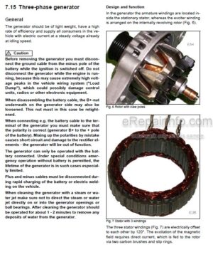
Generator
Electric Starter
-HYDRAULICS
Hydraulic Circuit
Travel Pump, A4VG56 HW
Vibration Pump, A10VG45 EZ
Axial Piston Swash-Plate Principle
Troubleshooting Axial Piston Pumps
Travel Motor 51C060
Vibration Motor A4Fm22/28
Vibration Valve
Steering Valve
External Gear Pumps
Overview Of Travel/Vibration Pump Connections
Travel Circuit
Towing
Vibration Circuit, Without Bam
Steering Circuit
Working Hydraulics
Fan Drive And Manifold Block With Thermostat
Check The Hydraulic Oil Level
Changing The Hydraulic Oil Filter
Changing Hydraulic Oil And Breather Filter
-TESTS AND ADJUSTMENTS
Special Tools, Tests And Adjustments
Checking The Rotation Speeds
Pressure Tests In The Travel Circuit
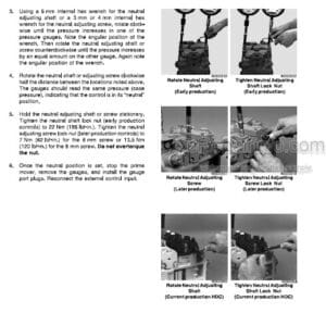
Checking / Adjusting The Neutral Positions Of The Travel Pump
Checking The Setting Of The High Pressure Relief Valves In The Travel Circuit
Pressure Tests In The Vibration Circuit
Check The Setting Of The High Pressure Relief Valves In The Vibration Circuit
Checking / Adjusting The Vibrator Shaft Speeds
Check The Leakage Rate Of The Vibration Motor
Pressure Test In Steering Circuit
-TROUBLE SHOOTING
Trouble Shooting
Trouble Shooting Chart – Travel System
Trouble Shooting Chart – No Vibration
Trouble Shooting Chart Steering System
Troubleshooting Axial Piston Pumps
Engine Problems
-FLUSHING AND BLEEDING
Special Tools For Flushing
Flushing – General
Flushing Schematic For Front Drum Drive
Flushing The Front Drum Drive
Flushing Schematic For Rear Drum Drive System
Flushing The Rear Drum Drive
Flushing Schematic For Wheel Drive Motors, Ac-Machines
Flushing The Rear Wheel Drive On Ac Machines
Flushing Schematic For Vibration Drive On Ad-Machines
Flushing Schematic For Vibration Circuit On Ac-Machines
Flushing The Vibration Circuit
Bleeding The Travel Circuit
Bleeding The Vibration Circuit
-ENGINE
Diesel Engine
Engine Description TCD 2012
Lubrication Oil Circuit TCD 2012 / 2013
Coolant Circuit TCD 2012/2013
Fuel System TCD 2012/2013
Deutz Common Rail (DCR) Injection System For TCD 2012 / 2013
Exhaust Gas Recirculation TCD 2012 / 2013
Adjust The Valve Clearance
Adjusting The Control Piston Play
General Trouble Shooting Chart TCD 2012 / 2013
Check The Engine Oil Level
Change The Engine Oil
Change The Engine Oil Filter Cartridge
Change The Fuel Filter Cartridge
Checking, Cleaning The Water Separator
Change The Fuel Pre-Filter Cartridge
Check The Coolant Level
Checking The Anti-Freeze Concentration
Change The Coolant
Checking The V-Belt, Tighten, If Necessary Replace The V-Belt
Check, Clean, Change The Combustion Air Filter
Replacing The Crank Case Ventilation Valve
Check The Engine Mounts
Electronic Injector Test EMR
Special Tools, Deutz Engine (TCD 2012 2V)
-AIR CONDITIONING SYSTEM
Physical Basics
Refrigerant R134A
Compressor Oil / Refrigeration Oil
Working Principle Of The Air Conditioning System
Monitoring Devices
Description Of Components
Measuring The Compressor Oil Level
Checking The Magnetic Clutch
Inspection And Maintenance Work
Servicing The V-Belt For The Refrigerant Compressor
Service The Air Conditioning
Drying And Evacuation
Emptying In Case Of Repair
Leak Test
Filling Instructions
Trouble Shooting In Refrigerant Circuit, Basic Principles
Trouble Shooting, Refrigerant Circuit Diagram
Trouble Shooting Procedure
Steam Table For R134A
-REPLACING THE CAB WINDOW PANES
Assembly Of Window Panes
Special Tools, Cabin Windows
Auxiliary Materials
Removing And Installing The Window Pane
-REPLACING THE TRAVEL CONTROL CABLE
Special Tools To Lift The Driver’s Stand, Tandem Rollers
Overview
Replacing The Travel Control Cable
-DRUM
Special Tools, Drum (BW161Ad-4 To BW203AD-4)
Repair Overview Ad-Drum
Removing And Installing The Drum
Dismantling The Ad-Drum
AD/AP Disassembling, Assembling The Exciter Unit
Assembling The Ad-Drum
-OSCILLATING ARTICULATED JOINT
Repair Overview Oscillating Articulated Joint
Removing – Disassembling The Oscillating Articulated Joint
Assembling The Oscillating Articulated Joint
-SUPPLIERS DOCUMENTATION
Travel Pump
Vibration Pump
Drum Drive
Drum Reduction Gear
Vibration Motor
Steering Valve
-CIRCUIT DIAGRAMS
Hydraulic Diagram
Wiring Diagram
What you get
You will receive PDF file with high-quality manual on your email immediately after the payment.


Reviews
There are no reviews yet.