


Factory Instructions For Repair For Bomag Single Drum Wheel Drive Vibratory Roller. Manual Contains Illustrations, Instructions, Diagrams For Step By Step Remove And Install, Assembly And Disassembly, Service, Inspection, Repair, Troubleshooting, Tune-Ups.
Format: PDF
Language: ENG
Pages: 810
Number: 00819094 (april 1988)
Wiring Diagrams: Yes
Hydraulic Diagrams: Yes
Model
Bomag Single Drum Wheel Drive Vibratory Roller
BW213
BW213D
BW213PD
BW213PDB
Contents
General Notes on Repairs
Safety
Torques
Conversion Table of Some Metric and Imperial Measures
Technical Data
Connection Surveys and Test Points
Special Tools
Genera! Description of Diesel Engine
Important Points on Trouble Shooting and Repair Work
Trouble Shooting
Trouble Shooting for Diesel Engine
Measuring the Diesel Engine Speed
Repair Work
Removing and Installing the Engine
Preparing the Engine for Travel
Exchanging the Axle
Special Tools for Repairing the Axle
Dismantling and Assembling the Power Take-Off
Dismantling and Assembling the Differential
Dismantling and Assembling the Differential (PDB)
Functional Description of Travel Drive BW 213 D/PD
Poclain Compact Motor
Important Points on Trouble Shooting and Repair Work
Trouble Shooting Chart
Trouble Shooting in the Travel Drive
Checks and Adjustments in the Travel Drive
Testing the Charge Pressure and the High-Pressure
Trouble Shooting, Travel Pump and Travel Motor
Trouble Shooting, Drum Drive Motor and Travel Pump
Measuring Leakage Oil Rate of the Drum Motor
Measuring Leakage Oil of the Travel Motor (Travel Speed 2)
Measuring Leakage Oil of the Travel Motor (Travel Speed 1)
Checking the Speed Selector
Checking the Cold Start and Charge Pressure Relief Valves
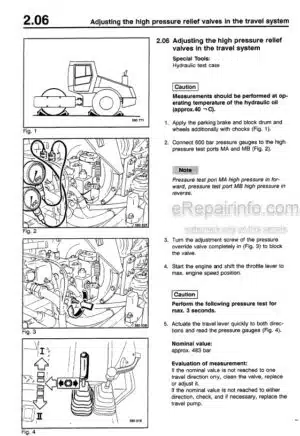
Exchanging the High Pressure Relief Valves
Checking the Travel Performance
Checking and Adjusting the Travel Actuation Cable/Pump
Control Lever
Repair Work
Exchanging the Drum Motor
Tools and Special Tools for the Drum Motor
Exchanging the Distributor Plate
Exchanging the Cylinder Block
Exchanging the Bearings
Travel Motor
Exchanging the Travel Motor
Exchanging the Radial Seal on the Travel Motor Shaft
Repairing the Travel Motor
Checking the Valve Plate and Cylinder Block
Anti-Tilt Device
Exchanging the Drive Shaft
Exchanging the Control Pistons in the Valve Plate Carrier
Limitation of Minimum Angle of Swing
Exchanging the Travel Pump
Exchanging the Travel Pump Coupling
Exchanging the Radial Seal on the Travel Pump Shaft
Repairing the Travel Pump
Exchanging the Radial Seal
Exchanging the Charge Pump
Checking/Exchanging the Valves
Checking/Exchanging the Valve Plate
Exchanging the Rear Tapered Roller Bearing on the Drive Shaft
Removing and Installing the Cylinder Drum
Checking the Axial Clearance of the Cylinder Drum
Removing and Installing the Drive Shaft
Detaching and Attaching the Housing Cover
Checking the Control Piston
Removing and Installing the Disc and Piston
Removing and Installing the Swash Plate
Removing the Control Cylinder
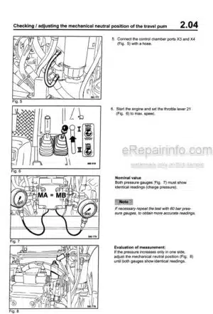
Checking the Mechanical Zero Position Setting
Travel Circuit
Flushing the Travel Circuit
Hydraulic System
Filling the Hydraulic System
Functional Description of the Vibration Drive BW 213 D/PD
Vibration 2 Amplitudes
Important Points on Trouble Shooting and Repair Work
Trouble Shooting Chart
Checks and Adjustments in the Vibration Circuit
Measuring the Speed of the Vibrator Shaft (Vibration
Frequency) (1 Amplitude)
Pressure Tests in the Vibration Circuit (1 Amplitude)
Checking the Vibration Pump (1 Amplitude)
Checking the Vibration Valve (1 Amplitude)
Checking the Electrical System of the Vibration Valve
Checking the Control Valve (Stop Valve) (1 Amplitude)
Measuring the Vibrator Shaft Speed (Vibration Frequency)
(2 Amplitudes)
Pressure Tests in the Vibration Circuit (2 Amplitudes)
Adjusting the Charge Pressure (2 Amplitudes)
Adjusting the High Pressure Relief and Pressure Cut-Off
(2 Amplitudes)
Adjusting the Vibrator Shaft Speed (Frequency) (2 Amplitudes)
Checking the Oil Leakage of the Vibration Motor
Repair Work
Removing and Installing the Drum
Exchanging the Rectangular Buffer (Left)
Exchanging the Rubber Buffer (Right)
Vibration Bearing Housing
Vibration Bearing Housing Bearing and Seals (old model)
Vibration Bearing Housing Bearing and Seals (new model)
Repairing the Drum
Exchanging the Vibration Motor
Exchanging the Radial Seal of the Vibration Motor
Cross-Section of the Vibration Motor
Sealing Kits/Assemblies
Sealing the Connection Plate
Removing and installing the Drive, Checking the Parts
Exchanging the Vibration Pump (One-Frequency Machine)
Exchanging the Radial Seal of the Vibration Pump
Exchanging the Coupling the Vibration Pump
Exchanging the Vibration Pump (BW 213 2A and 213 D 2A)
Repairing the Vibration Pump
Sealing the Drive Shaft of the Vibration Pump
Removing the Control Pressure Pipe
Removing the HP/LP Pressure Relief Valves,
Notes for Installation
Adjusting the HP/LP Pressure Relief Valve
Dismantling the Connecting Plate
Dismantling the Pump Housing
Dismantling the Drive
Dismantling the Hydraulic Adjusting Device
Assembling the Hydraulic Adjusting Device,
Notes for Adjusting the Mechanical Neutral Position
Notes for Adjustment: Locating Device (Return Force)
Repair and Adjustment Instructions AW with Control Unit EL
Repairing the Vibration Pump (One-Frequency Machine)
Flushing the Vibration Circuit (One-Frequency Machine)
Flushing the Vibration Circuit
Flushing the Virbation Circuit (BW 213 2A and BW 213 D 2A)
Functional Description of the Steering System
Steering, Neutral
Steering, Left
Emergency Steering
Important Points for Trouble Shooting and Repair Work
Trouble Shooting Chart
Trouble Shooting in the Steering System
Checks and Adjustments in the Steering System
Checking the Pressure in the Steering System
Steering Cylinder
Dismantling and Assembling the Steering Cylinder
Articulated Joint
Dismantling and Assembling the Articulated Joint
Removing and Installing the Steering Unit
Disassembling and Assembling the Steering Unit
Assembly
Assembling the Loop-Ring/Kin-Ring
Removing and Installing the Steering Pump
Exchanging the Steering Pump Seal Kit
Disassembling and Assembling the Valve Block,
Removing the Overflow Valve
Removing the Double Shock Valve
Installing the Shock Valve
Installing the Overflow Valve
Circuit Diagrams
Hydraulic Circuit Diagram
Electrical Circuit Diagram
What you get
You will receive PDF file with high-quality manual on your email immediately after the payment.


Reviews
There are no reviews yet