


Factory Service Manual For Bomag Single Drum Roller. Manual Contains Illustrations, Instructions, Diagrams For Step By Step Remove And Install, Assembly And Disassembly, Service, Inspection, Repair, Troubleshooting, Tune-Ups.
Format: PDF
Language: ENG
Pages: 1446
Number: 00891812 (june 2012)
Bookmarks: Yes
Searchable: Yes
Wiring Diagrams: Yes
Hydraulic Diagrams: Yes
Model
Bomag Single Drum Roller
BW216D-40
BW216PD-40
BW218D-40
S/N 101 583 39 ….
S/N 101 583 40 ….
S/N 101 583 41 ….>
Contents
-GENERAL
Introduction
Safety Regulations
General Repair Instructions
Tightening Torques
-TECHNICAL DATA
Technical Data
-MAINTENANCE
General Notes On Maintenance
Fuels And Lubricants
Table Of Fuels And Lubricants
Running-In Instructions
-CADDY WIRING DIAGRAMS
Understanding Circuit Diagrams
Circuit Symbols In The Circuit Diagram
Identification Of Switch Blocks In The Caddy Wiring Diagram
Designation Of Components In The Wiring Diagram
Terminal Designations In Wiring Diagram
-E-PLAN WIRING DIAGRAMS
Understanding Wiring Diagrams
Circuit Symbols In The Circuit Diagram
Identification Of Switch Blocks In The Wiring Diagram
Designation Of Components In The Wiring Diagram
Terminal Designations In Wiring Diagram
-ELECTRICS
Designation Of Components In The Wiring Diagram
Terminal Designations In Wiring Diagram
Battery Ground And Analog Ground
Current And Voltage
Resistance
Series / Parallel Connection
Ohm’s Law
Electrical Energy
Formula Diagram
Metrology
Diodes, Relays, Fuses
Telemecanique Switch
Plug Connectors
Magnetic Coil Plug
Deutsch Plug, Series DT And DTM
Plugs And Terminals In Spring Clamping Technology
Proximity Switches
Level Sensor In Diesel Tank (R03)
Differential Pressure Switch For Hydraulic Oil Filter, B21
Acceleration Transducer
Batteries
Service The Battery
Main Battery Fuse
Starting With Jump Wires
Generator
Replacing The Voltage Regulator
Electric Starter
Coolant Temperature Switch
Oil Pressure Switch And Low Oil Pressure Circuitry
Boost Fuel Solenoid Valve
Engine Shut-Down Solenoid
Electric Throttle Control
Heating Flange On Engine
Checking The Heating Flange Control
Engine Monitoring
Overview Of Electric Components
Operator’s Stand, Old Design
Operator’s Stand, New Design
Cabin
Fuses, Old Design
Fuses, New Design
Electronic Control Units
Checking The Voltage Supply For The Control Unit
Diagnostics Concept
-ELECTRONIC MODULES
BEM, Bomag Evib-Meter
Electrics Module A68
Electric Module K04
Electric Module A72, Old Design
Electric Module A108
-SPEEDOMETER MODULE
Speedometer Module
-582 502 15 DUST PROTECTION / 582 502 16 GASKET
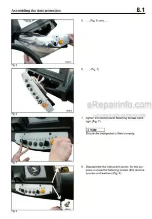
Assembling The Dust Protection
-HYDRAULICS
Hydraulic Circuit
Connection Overview
Travel Pump 075
Vibration Pumps 42R041 & 42R055
Axial Piston Swash Plate Principle / Pump
Troubleshooting Axial Piston Pumps
Travel Motor 51 C/D 110
Trouble Shooting, Variable Displacement Axial Piston Motor
Vibration Motor A10Fm 45
Vibration Motor 90M 055
Axial Piston Swash Plate Principle / Motor
External Gear Pumps
Travel Circuit
Adjust The Parking Brake
Stopping The Machine, Operating The Parking Brake
Towing In Case Of An Engine Failure
Vibration Circuit
Steering Circuit
Check The Hydraulic Oil Level
Changing Hydraulic Oil And Breather Filter
Replace Hydraulic Oil Filter
Changing The Bypass Filter
-TESTS AND ADJUSTMENTS
Special Tools, Tests And Adjustments
Adjusting The Solenoid For Engine Speed Control
Checking The Rotation Speeds
Checking / Adjusting The Neutral Positions Of The Travel Pump
Pressure Tests In The Travel Circuit
Checking / Adjusting The Vibrator Shaft Speeds
Pressure Measurements In The Vibration Circuit
Check The Leakage Rate Of The Vibration Motor
Pressure Test In Steering Circuit
-FLUSHING AND BLEEDING
Special Tools For Flushing
Flushing – General
Flushing Schematic Travel Circuit (Distribution Travel Pump)
Flushing The Travel Circuit (Travel Pump Distribution)
Flushing Schematic Travel Circuit (Distribution Axle Motor)
Flushing The Travel Circuit (Axle Motor Distribution)
Flushing Schematic For Vibration Drive
Flushing The Vibration Circuit
Bleeding The Travel Circuit
Bleeding The Vibration Circuit
-AIR CONDITIONING SYSTEM
Physical Basics
Refrigerant Rl34A
Compressor Oil / Refrigeration Oil
Working Principle Of The Air Conditioning System
Monitoring Devices
Description Of Components
Measuring The Compressor Oil Level
Checking The Magnetic Clutch
Inspection And Maintenance Work
Checking, Replacing The Refrigerant Compressor V-Belt
Air Conditioning Service (Old Design)
Service The Air Conditioning
Drying And Evacuation
Emptying In Case Of Repair
Leak Test
Filling Instructions
Trouble Shooting In Refrigerant Circuit, Basic Principles
Trouble Shooting, Refrigerant Circuit Diagram
Trouble Shooting Procedure
Steam Table For Rl34A
-CABIN ASSEMBLY
Preparations
Cabin Assembly
Final Function Tests And Checks
-REPLACING THE CAB WINDOW PANES
Assembly Of Window Panes
Special Tools, Cabin Windows
Auxiliary Materials
Removing And Installing The Window Pane
-DRUM
Special Tools, Drum, Single Drum Rollers
Repair Overview For Drum
Removing And Installing The Drum
Repairing The Drum
Dismantling, Assembling The Change-Over Weights
Changing The Rubber Buffers And Adjusting The Pretension
-OSCILLATING ARTICULATED JOINT
Special Tools, Oscillating Articulated Joint (BW177 To BW216)
Repair Overview Oscillating Articulated Joint
Removing And Installing The Oscillating Articulated Joint
Dismantling The Oscillating Articulated Joint
Assembling The Oscillating Articulated Joint
-SUPPLIERS DOCUMENTATION
Travel Pump
Vibration Pump
Travel Motor
Vibration Motor
Vibration Motor
Drum Reduction Gear
Steering Valve
Axle
Diesel Engine
-CIRCUIT DIAGRAMS
Hydraulic Diagram
Wiring Diagram
What you get
You will receive PDF file with high-quality manual on your email immediately after the payment.


Reviews
There are no reviews yet