


Factory Service Manual For Case Loader. Manual Contains Illustrations, Instructions, Diagrams For Step By Step Remove And Install, Assembly And Disassembly, Service, Inspection, Repair, Troubleshooting, Tune-Ups.
Format: PDF
Language: English
Pages: 813
Number: 9-69100 (january 1980)
Bookmarks: Yes
Wiring Diagrams: Yes
Hydraulic Diagrams: Yes
Model
Case Loader
W14
Contents
-GENERAL
General Engine Specifications
Detailed Engine Specifications
Maintenance and Lubrication
Torque Chart
-ENGINE
Engine Diagnosis
Engine Tune-Up
Cylinder Head, Valve Train and Camshaft
Cylinder Block, Sleeves, Pistons and Rods
Crankshaft, Main Bearings, Flywheel and Oil Seal Replacement
Lubrication System
Stall Checks and Engine Removal and Installation
Backhoe Throttle Cable Adjustment
Air Cleaner and Spark Arrester
Cooling System
-FUEL SYSTEM
Fuel System and Filters
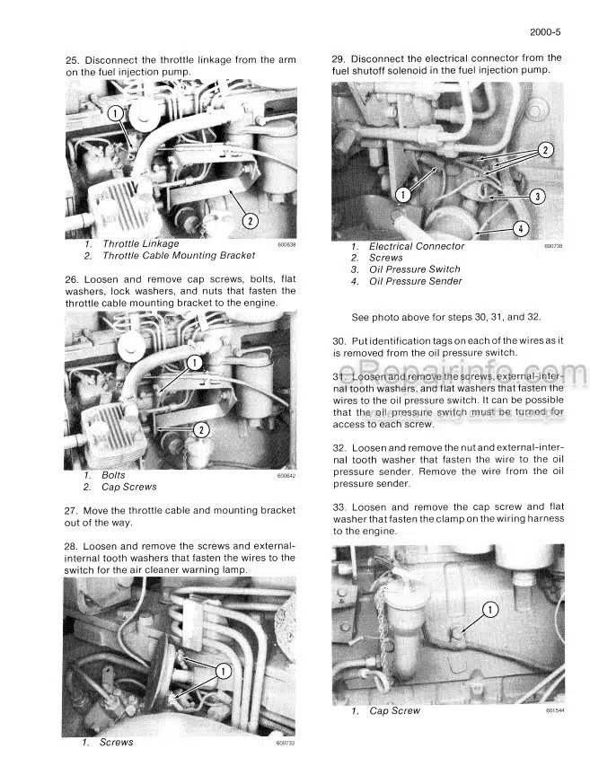
Robert Bosch Fuel Injection Pump
Roosa Master Fuel Injectors
Electric Fuel Pump
Fuel Lines and Fuel Tank
-HYDRAULICS
Hydraulic Diagram, Trouble Shooting, Testing and Adjustments
Backhoe Hydraulic Diagrams, Trouble Shooting, Pressure Checks
Hydraulic Pump
L51290 and L52776 Loader Control Valves
Case Backhoe Control Valve
L55038 Diverter Valve
L56060 Backhoe Relief Valve
Loader Cylinders
Backhoe Cylinders
-STEERING
Hydraulic Diagram, Trouble Shooting and Testing
Steering Control Valve and Flow Control Valve
Steering Cylinders
Center Pivot
-POWER TRAIN
Allison Transmissions – Powershift Model
Transmission Removal and Installation
Differentials and Planetaries
Rear Axle Trunnion Center Bearing Support, Drive Shafts and Universal Joints
-BRAKES
Air System Operation and Diagram
Pressurizing/Depressurizing the Air System
Brake Shoes and Wheel Cylinders
L52092 Air Compressor, Governor and Reservoir
L17683 Air Compressor
Brake Valve
Brake Actuator
Parking Brake Actuator and Control Valve
Pressure Protection Valve and Pressure Reducing Valve
Air Horn and Horn Valve
Alcohol Evaporator
Double Check Valve/Stop Light Switch
-ELECTRICAL
Wiring Diagram – Machines without Instrument Clusters,
Trouble Shooting and Adjustments
Batteries
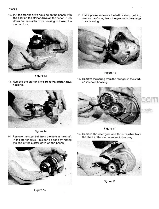
Starter, Starter Solenoid and Magnetic Switches
35 amp Alternator, (Models without Instrument Cluster)
30 amp Alternator, (Models with Instrument Cluster)
-MOUNTED EQUIPMENT
Loader
Model 26 C Backhoe
Roll-Over Protection Structure
What you get
You will receive PDF file with high-quality manual on your email immediately after the payment.


Reviews
There are no reviews yet