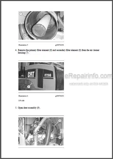
Factory Repair Manual For Caterpillar 924G, 924GZ Wheel Loader. Illustrations, instructions, diagrams for step by step remove and install, assembly and disassembly, service, inspection, repair, troubleshooting, tune-ups.
Format: PDF
Language: English
Pages: 4418
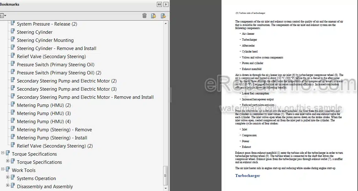
Bookmarks: Yes
Searchable: Yes
Wiring Diagrams: Yes
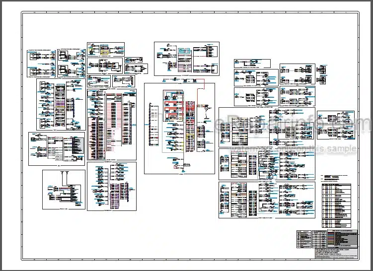
Hydraulic Diagrams: Yes
Model
Caterpillar 924G; 924GZ
924G:
DDA1-UP
WMB1-UP
RBB1-UP
924GZ:
WGX1-UP
DFZ1-UP
RTA1-UP
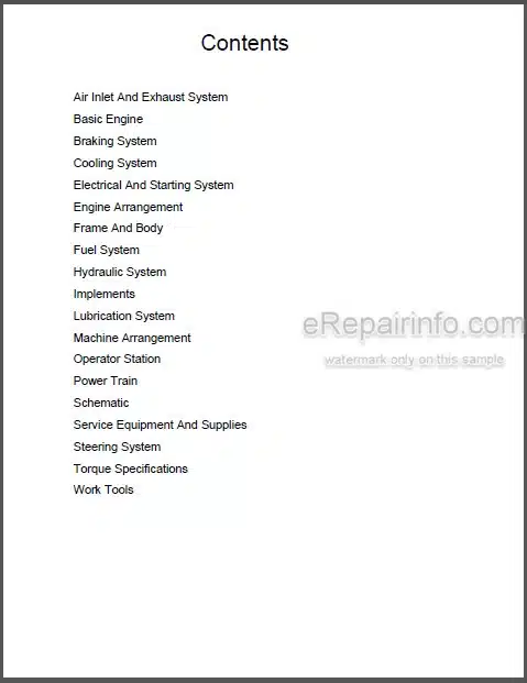
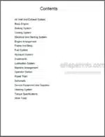
Contents
-AIR INLET AND EXHAUST SYSTEM
Systems Operation
Testing and Adjusting
Troubleshooting
Specifications / Disassembly and Assembly
-BASIC ENGINE
Systems Operation
Testing and Adjusting
Troubleshooting
Specifications / Disassembly and Assembly
-BRAKING SYSTEM
General Information (Braking)
Gear Pump (Braking and Hydraulic Fan)
Brake Accumulator
Brake Control Valve (Service)
Parking Brake
System Pressure – Release
Hydraulic Oil Contamination – Test
Brake Accumulator – Test and Charge
Service Braking System Pressure – Test
Service Brake Control (Pedals) – Adjust
Service Brakes – Test
Brake System Air – Purge
Parking Brake – Test
Parking Brake – Manual Release
Parking Brake Control – Adjust
Machine Preparation for Troubleshooting
Visual Inspection
Operational Checks (Brake, Hydraulic Fan System)
Brake and Hydraulic Fan System
MID 081 – CID 0070 – FMI03
MID 081 – CID 0070 – FMI 04
Hydraulic Tank
Oil Filter (Hydraulic)
Brake Accumulator – Remove and Install
Brake and Planetary
Parking Brake – Remove
Parking Brake – Install
Service Brakes – Remove and Install – Single Disc Brakes
Pressure Sensor (Brake Oil)
Limit Switch (Parking Brake)
Solenoid Valve (Brake Charging)
Pressure Sensor (Brake Charging)
Gear Pump (Braking and Hydraulic Fan) – Remove
Gear Pump (Braking and Hydraulic Fan) – Install
-COOLING SYSTEM
Systems Operation
Testing and Adjusting
Troubleshooting
Specifications / Disassembly and Assembly
-ELECTRICAL AND STARTING SYSTEM
Systems Operation
Testing and Adjusting
Troubleshooting
Specifications / Disassembly and Assembly
-ENGINE ARRANGEMENT
Testing and Adjusting
Specifications / Disassembly and Assembly
-FRAME AND BODY
Specifications / Disassembly and Assembly
-FUEL SYSTEM
Systems Operation
Testing and Adjusting
Troubleshooting
Specifications / Disassembly and Assembly
-HYDRAULIC SYSTEM
Systems Operation
Testing and Adjusting
Troubleshooting
Specifications / Disassembly and Assembly
-IMPLEMENTS
Specifications / Disassembly and Assembly
-LUBRICATION SYSTEM
Systems Operation
Testing and Adjusting
Troubleshooting
Specifications / Disassembly and Assembly
-MACHINE ARRANGEMENT
Systems Operation
Testing and Adjusting
Troubleshooting
-OPERATOR STATION
Systems Operation
Testing and Adjusting
Troubleshooting
Specifications / Disassembly and Assembly
-POWER TRAIN
Systems Operation
Testing and Adjusting
Troubleshooting
Specifications / Disassembly and Assembly
-SCHEMATIC
RENR6432-01
RENR6434-04
RENR8733-04
RENR9695-02
Fluid Power Graphic Symbols
-SERVICE EQUIPMENT AND SUPPLIES
Systems Operation
Testing and Adjusting
Troubleshooting
Specifications / Disassembly and Assembly
-STEERING SYSTEM
General Information (Steering)
Piston Pump (Steering and Pilot)
Metering Pump (HMU)
Secondary Steering System – If Equipped
Secondary Steering Pump and Electric Motor
System Pressure – Release
Hydraulic Oil Contamination – Test
Pump Performance (Steering) – Test
Piston Pump (Steering and Pilot) Low Pressure Standby – Test and Adjust
Piston Pump (Steering and Pilot) High Pressure Stall – Test and Adjust
Piston Pump (Steering and Pilot) Margin Pressure – Test and Adjust
Steering Wheel Slip – Check
Metering Pump (HMU) – Test
Machine Preparation for Troubleshooting
Visual Inspection
Steering System
Hydraulic Tank
Oil Filter (Hydraulic)
Steering Cylinder
Steering Cylinder Mounting
Steering Cylinder – Remove and Install
Relief Valve (Secondary Steering)
Pressure Switch (Primary Steering Oil)
Secondary Steering Pump and Electric Motor – Remove and Install
Metering Pump (HMU) (2)
Metering Pump (HMU) (3)
Metering Pump (HMU) (4)
Metering Pump (Steering) – Remove
Metering Pump (Steering) – Install
-TORQUE SPECIFICATIONS
Torque Specifications
-WORK TOOLS
Systems Operation
Disassembly and Assembly
What you get
You will receive PDF file with high-quality manual on your email immediately after the payment.

Reviews
There are no reviews yet.