


Factory Service Repair Manual For Claas Renault Ceres 316 326 336 346 Tractors. Tons of illustrations, instructions, diagrams for step by step remove and install, assembly and disassembly, service, inspection, repair, troubleshooting, tune-ups.
Format: PDF
Language: English
Bookmarks: Yes
Searchable: Yes
Wiring Diagrams: Yes
Hydraulic Diagrams: Yes
Model
Claas Renault Ceres 316, 326, 336, 346
Contents
-ENGINE Ceres 326 – 336 – 346
–GENERAL SPECIFICATIONS
Engine Specifications
Fuel System Data
Service Data And Tolerances
Tightening Torque
Longitudinal Section
Cross Section
Lubrication System
Cooling System
Fault Diagnosis Chart
–ENGINE REMOVAL & INSTALLATION
Engine Removal
Engine Installation
–ENGINE DISASSEMBLING & ASSEMBLING
Engine Disassembling
Engine Assembling
–CHECKS, DIMENSIONS & REPAIRS
Cylinder Block and Cylinder Liner
Crankshaft, Main Bearing and Flywheel
Connecting Rods
Pistons
Camshaft, Tappets and Valves
Cylinder Head
Valve Guides
Valve Seat In Cylinder Head
Injector Sleeves
Rotating Counterweight Dynamic Balancer
Lubrication System
Cooling System
Coolant Pump and Alternator Drive Belt
Engine Compression Test
–SUB ASSEMBLY REMOVAL / INSTALLATION & SETTING
Crankshaft Front Oil Seal
Coolant Pump
System Thermostat Cooling
Bosch Injection Pump
Fuel Injectors
Valve Clearance Adjustment
Water Pump
–TOOLS
Special Tools
-ENGINE Ceres 316
–GENERAL SPECIFICATIONS
Engine Specifications
Service Data
Longitudinal Section
Cross- Section
Lubrication Chart
Fault Diagnosis Chart
Key to Fault Diagnosis Chart
–ENGINE REMOVAL & INSTALLATION Refer to Al Chapter for Engine removal Procedure
—DISASSEMBLING – ASSEMBLING
Engine Assembly
Engine Trimming
–TOOLS
Tools
Special Tools
General Tools
-CLUTCH
–SPECIFICATIONS
Clutch Specifications
Cross Section
Tightening Torque and Adjustments
–DRIVE & POWER TAKE-OFF MECHANICAL CLUTCHES
Clutch Removal
Clutch Disassembly
Clutch Inspection
Friction Disc Inspection
Clutch Re-assembly
Inspection and Reconditioning Of The Engine Flywheel Thrust Surfaces
Inspection Of The Engine Flywheel Spigot Bearing
Engine Flywheel Removal & Installation
Clutch Installation
Clutch Lever Adjustment
–THRUST BEARINGS AND GUIDE
Removal / Installation Of The Trust Bearing and Guide
–DRIVE & POWER TAKE-OFF CLUTCH CONTROL
Drive Clutch Control
Power Take-off Clutch Control
-GEARBOX
–PRIMARY SHAFT
Introduction
Preliminary Operations
Removal / Installation Of The Primary Shaft
–SECONARY SHAFT
Introduction
Preliminary Operations
Removal I Installation Of The Secondary Shaft
Removal / Installation Of The Drive Intermediate Shaft
Adjustment Of The Pinion Protrusion
Final Operations
Types Of Interventions On Secondary Shaft
–FRONT INTERMEDIATE SHAFT
Introduction
Preamble
Preliminary Operations
Removal I Installation Of Shaft
Adjustment
Final Operations
–REAR INTERMEDIATE SHAFT
Introduction
Preamble
Preliminary Operations
Removal/Installation Of Shaft
Pre-loading The Bearings
Final Operations
–SPECIFICATIONS
Gearbox Specifications
Mechanical Gearboxes Kinematics
Adjustments and Tightening Torque
Casing Tightening Torque
Cover Tightening Torque
–GEARBOX CONTROLS
Gearboxes with Mechanical Reverser
Gearboxes with Mechanical Gear Shuttier and Reverser
Gearboxes with Creeper Range + Mechanical Gear Shuttier and Reverser
Control Locking
Adjustment of the Mechanical Controls
–POWER TAKE-OFF CLUTCH SHAFT
Removal / Installation Of The Power Take-off Shaft
–INPUT HOUSING
Drive Shaft
Input Housing With Mechanical Reveser
Input Housing With Mechanical Reveser + Shuttier
Input Housing With Mechanical Reveser + Shuttier + Creeper Range
Removal I Installation
Adjustment of the Reverser / Splitter Drive Clearance
Adjustment of the Bearing Preload
–TOOLS
Gearbox Tools
-LOW PRESSURE HYDRAULIC SYSTEM
–PRESENTATION
Tightening Torque For The Hydraulic Components And Fittings
Principle Diagram
Pressure Restrictor
Flow Divider/ Regulator
Hydraulic Unit
–HYDRAULIC CHECKS
Hydraulic Controls
“Checking Values Reading” Sheet
–TOOLS
Hydraulic Tools
-REAR AXLE
–PRESENTATION
Specifications
Kinematics
Attachment points
Adjustment And Tightening Torque
Power Take-Off
–POWER TAKE-OFF
General
Removal / Installation
–DIFFERENTIAL SHAFTS
Section View
Removal / Installation
–DIFFERENTIAL CROWN WHEEL AND PINION
Removal / Installation Of The Crown Wheel And Pinion
Adjustment Of The Pre-load Of The Bearing
Checking The Clearance Of The Crown Wheel Teeth
Changing The Crown Wheel
Changing The Rear Axle Casing
–AXLE TUBES AND SHAFTS
Removal / Installation Of The Axle Tubes And Shafts
Adjustment Of The Shaft End Float
Final Operations
–DIFFERENTIAL LOCK / RELEASE CONTROLS
Description
Removal / Installation Of The Differential Lock Mechanism
Adjustment Of The Differential Lock Inside Mechanism
–TOOLS
Rear Axle Tools
-BRAKE
–SERVICE BRAKES – HANDBRAKE
Specifications
Brake Removal / Installation
Brake Control Adjustment
–TOOLS
Brake Tools
-FRONT AXLE (4WD)
–PRESENTATION
General Specifications
Kinematics
–REMOVAL / INSTALLATION
Wheel Alignment adjustment
Preliminary Operations
Reducers And Wheel Hubs
2011 And 2014 Front Axle Tightening Torque And Tools
Planet Gear Reducer
Differential
Wheel Pivots – Universal Joint Shafts
Differential – Bevel Gear
Adjustment For The Bevel Gear Preload
Adjustment For The Apex Distance
Backlash Adjustment
Preload Of Differential Bearings
Final Operations
–TOOLS
Front Axle 4WD Tools
-4 WHEEL DRIVE DROP BOX
–4WD DROP BOX
Safety Devices
Tightening Torque Adjustments
Removal I Installation
4WD Housing Removal
Belville Spring Assembly Shimming
Piston Stroke Shimming
4WD Housing Installation
Bearing Clearance Adjustment
Operating Check
Final Operations
4WD Drop Box Clutch Control
–TOOLS
4WD Power Take Off Housing Tools
-FRONT AXLE (2WD)
–PRESENTATION
General Specifications
–REMOVAL / INSTALLATION
Disassembly Of Tie Rod
Servicing Of Wheel End Assembly
Axle Tread Adjustment
Disassembly / Assembly Of Tie Rod Cylinder
–SPECIFICATIONS
Torque Values And Other Specifications
Service Frequency
Trouble Shooting
-HYDRAULICS
–PRESENTATION
General Specifications
Hydraulic Controls
Hydraulic circuit
Schematic Diagram
Hydraulic Components And Unions Tightening Torque
–REMOVAL / INSTALLATION OF THE ELEMENTS
Brake Valve
Flow Divider
Auxiliary Valves
Auxiliary Distributors – Overall View
Changing The Suction Strainer
Changing The Filtering Cartridge
Changing The Breather
Bleeding The Air
Changing The Pump
–MEASUREMENT POINTS AND CHECKS
Checking Values Reading Sheet
–TOOLS
Hydraulic Tools
-LIFT HITCH
–PRESENTATION
General Specifications
Hydraulic Unions Tightening Torque
Hydraulic Controls
Main Distributor
Schematic Diagrams Of The Distributor
–REMOVAL / INSTALLATION
Disassembly Of Tie Rod
Lift Casing
Lift Arm And Piston
Internal Controls
Control Levers
Hydraulic Distributor
Position Control Lever Adjustment
Draft Control Lever Adjustment
Draft Sensor Lever Adjustment
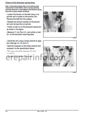
Checking Forces On The Flexion Bar
Lower Link Bearing Clearance
Draft And Position Control Adjustment
–DIAGNOSTIC
Sheet №1: No Descent – Hitch Loaded
Sheet №2: No Rise Or Slow Rise
Sheet №3: Lack Of Stability (Jerking)
–TOOLS
Lift Tools
-STEERING
–PRESENTATION
Specifications
General
Schematic Diagrams
–REMOVAL/INSTALLATION
Steering Unit
–CHECKS AND ADJUSTMENTS
Steering Unit
Shock Valves
Steering Cylinder
Pump Flow Check
–DIAGNOSTIC
Wheel Hard To Steer
Abnormal Vibration In The Wheel – Oscillation In The Steering Inaccurate Steering – Path Correction
–TOOLS
Steering Tools
-ELECTRICS
Fuse Box
Starting Circuit
Charging Circuit
Dipped Beam – Main Beam – Hom
Revolving Light
Front And Rear Work Light
Brake Lights – Front Axle Engaging / Control
Side Lights – Number Plate Lighting – Instrument Panel Lighting Indicators And Hazard Warning Lights
Instrument Panel – Fuel Gauge – Oil Pressure Gauge – Engine Temperature – Air Filter Clogging
Hand Brake
Engine Speed – Tachometer Input
Power Supply Socket – 20A
What you get
You will receive PDF file with high-quality manual on your email immediately after the payment.


Reviews
There are no reviews yet.