


Factory Service Repair Manual For Fiat 780, 780 DT, 880, 880 DT Tractors. Tons of illustrations, instructions, diagrams for step by step remove and install, assembly and disassembly, service, inspection, repair, troubleshooting, tune-ups.
Format: PDF
Language: English
Pages: 216
Bookmarks: Yes
Searchable: Yes
Number: 603.54 201
Wiring Diagrams: Yes
Hydraulic Diagrams: Yes
Model
Fiat
780 – 780 DT
880 – 880 DT
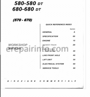
Contents
- – SPECIFICATION
Identification data – Weights
Engine
Power Train – Brakes – Steering – Front Axle
Drive Train Diagrams
Front Axle – Rear Wheels – Power Take Off
Lift – Towing Attachments
Ballasting – Body – Electrical System
Lighting – Instruments and Accessories –
Tyre Size
Dimensions
Capacities - – ENGINE SPECIFICATION AND DATA
Engine Block – Cylinder Head
Crank Gear
Crank Gear
Valve Gear
Valve Gear
Lubrication System
Cooling System
Fuel System
Tightening Torque Figures
Longitudinal Section through Engine
— 780 Tractor
— 880 Tractor - – ENGINE – DESCRIPTION
To Remove – To Refit
Description
Performance Data
Compression Test
To Remove – To Refit
Performance Data - – ENGINE – ENGINE BLOCK – CYLINDER HEAD
Cylinder Liners
Cylinder Head - – ENGINE – FUEL SYSTEM
Not available - – ENGINE – LUBRICATION SYSTEM
Lubrication System Diagram
— 780 Tractor
— 880 Tractor
Oil Pump – Oil Filter – Oil Pressure
Warning System - -ENGINE – Cooling System
Cooling System Diagram
Description – Water Pump
Radiator
To Adjust Belt Tension – Water Temperature
Gauge – Thermostat - – POWER TRAIN – SPECIFICATION AND DATA
Clutches
Gearbox and Splitter
Crawler Gear 6
Rear Bevel Drive and Differential
Brakes
Final Drives
Power Take Off
Tightening Torque Figures
Cross Section through Power Train
— 780 Tractor 13
— 880 Tractor 14
Longitudinal Section through Power Train
— 780 Tractor 15
— 880 Tractor 16 - – POWERTRAIN – TO REMOVE AND REFIT
Control Platform
102 – ENGINE – Valve Gear
Camshaft – Valves, Guides and Springs
Tappets, Pushrods and Rockers
Valve Timing Gear Train - – ENGINE – CRANK GEAR
Crankshaft
Main and Big-End Bearings and Caps
Pistons and Rings
Connecting Rods
Flywheel
Dynamic Balancer
— 780 Tractor
— 880 Tractor - – POWER TRAIN – CLUTCH
To Remove and Refit
To Overhaul Ferodo Clutch
To Adjust Ferodo Clutch
To Overhaul Luk or O.M.G. Clutches
To Adjust Luk or O.M.G. Clutches
To Adjust Clutch Linkage - – POWER TRAIN – GEARBOX AND SPLITTER
To Remove – To Refit – To Dismantle
Sections through Gearbox - – 780, 8-speed
- – 880, 8-speed
780 12-speed
880 12 speed, PM
To Inspect -To Reassemble
To Adjust Gearbox, 880Tractor - – POWER TRAIN – CRAWLER GEAR
Description – Overhaul 8-speed Transmission
Description – Overhaul, 12-speed Transmission - – POWER TRAIN – REAR BEVEL DRIVE DIFFERENTIAL
To Remove – To Refit – To Dismantle
To Reassemble
To Adjust Bevel Drive
Sections through Bevel Orive and Differential
To Adjust Differential
To Reassemble and Readjust Differential Lock
To Adjust Differential Lock Control Pedal - – POWER TRAIN – BRAKES OPERATION
To Dismantle and Reassemble Brake Units
To Dismantle and Reassemble Master Cylinder
To Adjust the Pedals
To Reinstall the Pedals – To Bleed the System
To Bench Test Master Cylinder
Parking Brake - – POWER TRAIN – FINAL DRIVES
To Remove – To Dismantle
To Reassemble
To Refit - – POWER TRAIN – POWER TAKE-OFF
To Remove – To Refit
To Dismantle – To Reassemble - – FRONT AXLE – STEERING – SPECIFICATION AND DATA
Front Axle
Manual Steering – Power Steering
Tightening Torque Figures - – FRONT AXLE – STEERING – FRONT AXLE
To Remove and Refit Axle Beam – To Overhaul Axle Arms
To Inspect - – FRONT AXLE – STEERING – MANUAL STEERING
To Overhaul Steering Box
Linkage - – FRONT AXLE – STEERING- POWER STEERING
To Overhaul Power Steering
To Overhaul Hydraulic Steering
To Overhaul Steering Pump and Reservoir – To Bleed the System
To Adjust the Valves
To Adjust the Valves
Fault Finding Chart
Operation Diagram and Section - – LIVE FRONT AXLE – SPECIFICATION AND DATA
Front Axle
Front Axle Drive -Drive Shaft
Tightening Torque Figures - – LIVE FRONT AXLE – FRONT AXLE
To Overhaul Final Drives Steering Joints
To Remove -Hubs and
To Adjust King Pm Bearings – To Adjust Wheel 8earmgs
To Overhaul Bevel Drive and Differential
To Adjust Bevel Drive
To Adjust Differential - – LIVE FRONT AXLE – DRIVE SHAFTS-AXLE DRIVE
To Remove and Refit Drive Shafts – To Dismantle Axle Drive
To Reassemble Axle Drive
Sections through Live Front Axle - – LIFT UNIT – SPECIFICATION AND DATA
Lift
Lift Pump
Implement Attachment
Fault Finding Chart
Tightening Torque Figures - – LIFT UNIT – LIFT
Description
To Remove – To Dismantle
Hydraulic System Diagrams
Lift Schematics
To Inspect
To Reassemble
To Adjust
To Adjust Relief and Cylinder Safety
Valves
To Check Drain Valve - – LIFT UNIT – LIFT PUMP
To Overhaul
Output Test – Oil Fitter - – LIFT – AUXILIARY CYLINDER
Main Data
Torque Figures
Hydraulic System Diagram - – LIFT UNIT – IMPLEMENT ATTACHMENT
Three-point Linkage – Draught Control
To Adjust Sensing Bar End Float . . . - – LIFT UNIT – REMOTE CONTROL VALVES
Main Data
Tightening Torque Figures
To Dismantle
Description and Operation
To Adjust Relief Valve
To Check Spool Return
To Check for Leakage - – ELECTRICAL SYSTEM – SPECIFICATION AND DATA
Charging System
Starter
— Marelli
— Marelli
— Bosch
— Bosch
Battery – Fuses
Lighting – Signals – Accessories
Starter Switch – Lighting Switch – Direction
Light Switch
Controls and Instruments
C.A.V. Start Retard Device
Wiring Diagrams - – SERVICE TOOLS
What you get
You will receive PDF file with high-quality manual on your email immediately after the payment.


Anonymous (verified owner) –
Was sceptic at first. But the review online where good. So I took the plunge.
I did get the book. The right book. No their fault by the book did not have the only section I wanted in the first place. The fuel system section was ” unavailable” in this shop manual… So yeh. But good news is this guys are not a scam.