Factory Technical Handbook And Option For Fiat Kobelco Wheel Loader. Manual Contains Illustrations, Instructions, Diagrams For Step By Step Remove And Install, Assembly And Disassembly, Service, Inspection, Repair, Troubleshooting, Tune-Ups.
Format: PDF
Language: English
Quantity of Manuals: 2
Pages: 594; 50
Number: 604.06.995.02 (july 2002); 604.13.348 (april 2004)
Bookmarks: Yes
Searchable: Yes
Wiring Diagrams: Yes
Hydraulic Diagrams: Yes
Model
Fiat Kobelco Wheel Loader
W50
W60
W70
Contents
1. Fiat Kobelco W50 W60 W70 Technical Handbook Wheel Loader 604.06.995.02.
2. Fiat Kobelco W50 W60 W70 High Travel Speed Option Wheel Loader 604.13.348.
1. Fiat Kobelco W50 W60 W70 Technical Handbook Wheel Loader 604.06.995.02.
-GENERAL
Foreword
And Additional Units
Conversions Tables
Calculation Examples
Tightening Torques
-SERVICE DATA
Foreword
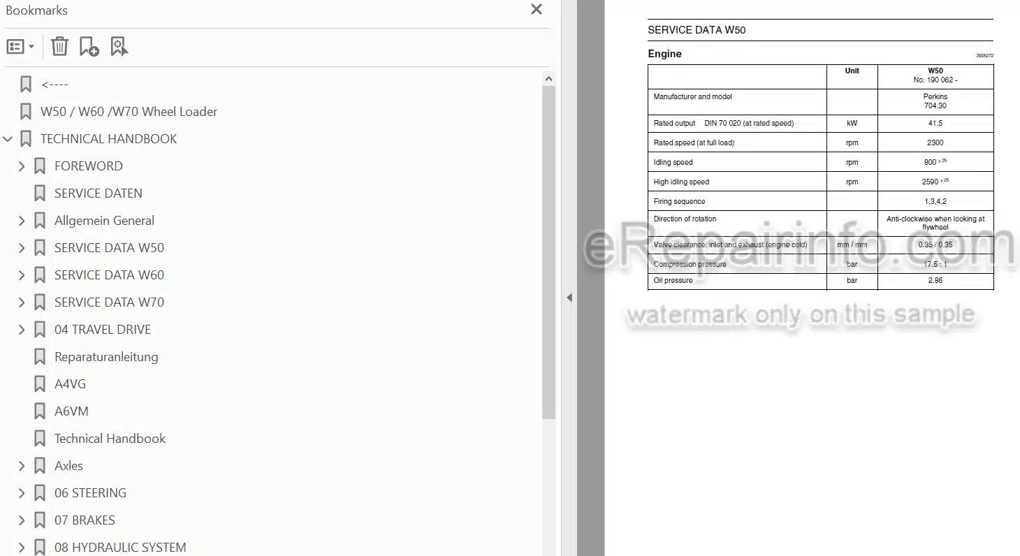
Engine
Axles And Transmission Gears
Travel Speeds
Hydraulic System
Service Fluids
Tightening Torques
Approx Weights
-TRAVEL DRIVE
Hydraulic System, Safety Instructions
Explanations Of Circuit Diagrams And Illustrations
Depressurizing The Hydraulic System
Principle: Hydrostatic Travel Drive
Hydraulic Circuit Diagram – Travel Drive
Hydraulic Circuit Diagram, Legend
Functional Description: Hydrostatic Travel Drive Of Wheel Loader W50 / W60 / W70
Adjusting Work At The Hydrostatic Travel Drive
Repair Instructions, Hydraulic Pump
Repair Instructions, Hydraulic Motor
-AXLES
General
Survey
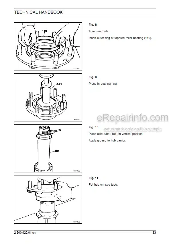
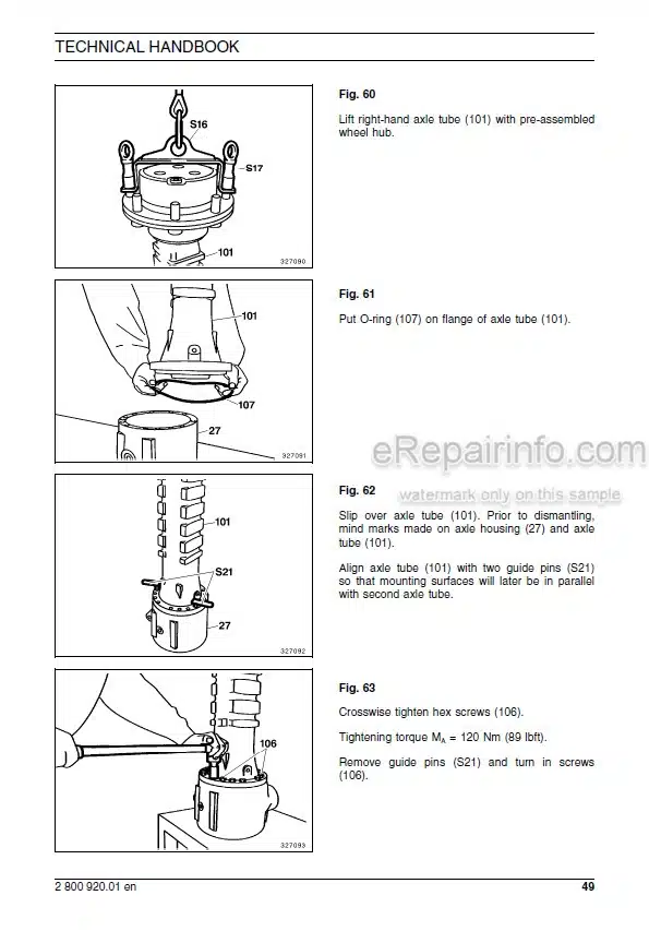
Dismantling and Reassembling the Axles
Dismantling the Front Axle
Dismantling the Rear Axle
Assembling the Front Axle
Assembling the Rear Axle
GLEASON Toothing Surface Appearances
List of Special Tools
Screw Tightening Torques (DIN tables)
Screw Tightening Torques
-STEERING
Hydraulic System, Safety Instructions
Explanations Of Circuit Diagrams And Illustrations
Depressurizing The Hydraulic System
Hydraulic Circuit Diagram – Steering Hydraulics
Hydraulic Circuit Diagram, Legend
Overview Of The Steering System
Functional Description
Triple Pump (2) Of The Steering And Working Hydraulics And The Brake System
Priority Valve (L6)
Steering Cylinder (L1)
Steering Valve (L2)
Installing The Steering System
Testing And Adjusting The Steering System
-BRAKES
Safety Instructions
Explanations Of Circuit Diagrams And Illustrations
Braking System, Circuit Diagram
Braking System, Legend
Functional Description Of The Braking System
Testing And Adjusting The Service Brake
Checking The Brake Disks
Testing And Adjusting Operations On The Auxilliary Brake
Testing And Adjusting Operations On The Parking Brake
Bleeding The Braking System
-WORKING HYDRAULIC
Hydraulic System, Safety Instructions
Explanations Of Circuit Diagrams And Illustrations
Depressurizing The Hydraulic System
Hydraulic Circuit Diagram – Working Hydraulics
Hydraulic Circuit Diagram, Legend
Functional Description, Working Hydraulics
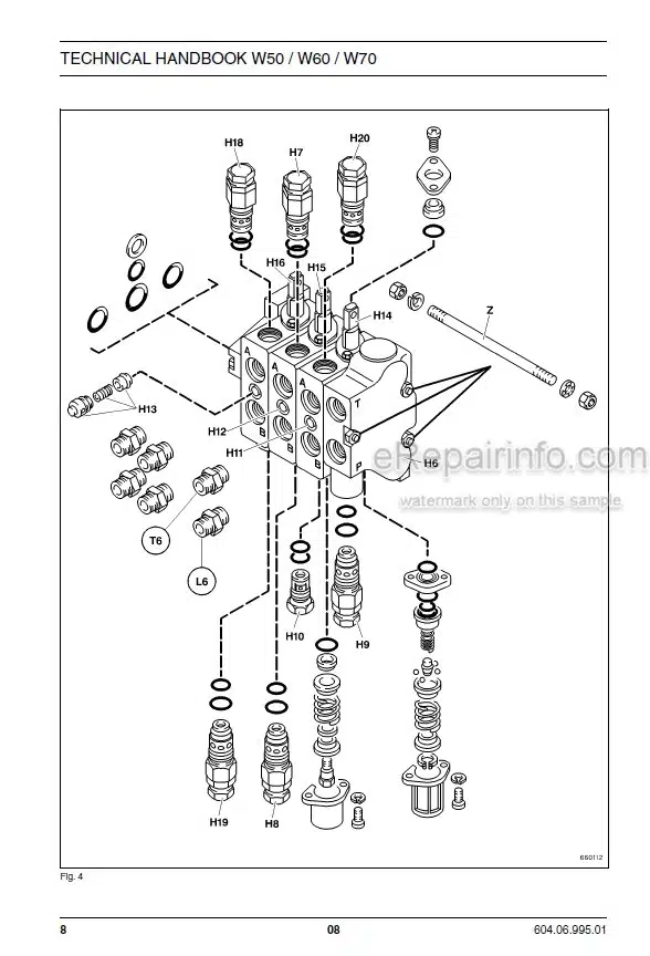
Control Block (H6)
Triple Pump (2) Of The Steering And Working Hydraulics And The Brake System
Lifting Cylinder (H1)
Dumping Cylinder (H2)
Quick Change Locking Cylinder (H3)
Hydraulic Tank (T1) / Hydraulic Filter (T3)
Hydraulic Filter (T3), Function
Hydraulic Circuit Diagram – Cooling
Hydraulic Circuit Diagram, Legend
Functional Description Of Hydraulic System Cooling
Practical Checking
Combined Cooler (T2)
Distributor (T5)
Distributor (T6)
Testing And Adjustment Work
Pipe-Burst Protection (Optional)
-ELECTRICAL SYSTEM
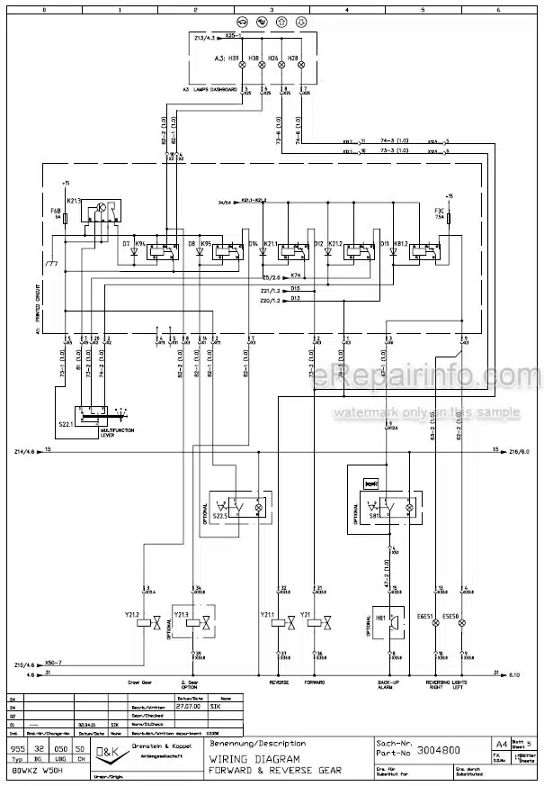
Electrical Components In Circuit Diagram, P/No 3 004 800
Technical Handbook “Fundamentals Of Electrical Engineering”
Technical Handbook “Interpretation Of Wiring Diagrams”
-FUNDAMENTALS OF ELECTRICAL ENGINEERING
Preface
Important Instructions
Electrical Systems In General
Power Generation
Main Components Of Automotive Electrical Systems
Fundamentals Of Automotive Electrical Systems
Measurements With The Multimeter
Series And Parallel Connection Of Electrical Components
Voltage Losses And Cables
Lighting
Special Circuits In Automotive Electrical Systems
Fuses In Motor Vehicles
Designation Of Individual Components
Standardized Designations Of Terminals
-AUTOMOTIVE ELECTRICAL SYSTEMS IN CONSTRUCTION MACHINERY INTERPRETATION OF WIRING DIAGRAMS TROUBLESHOOTING
Preface
Notes On Safety
Electrical System Documentation
The Wiring Diagram
Wiring Diagram Legend
Checking And Testing Equipment
Basic Measuring And Testing Procedures
Practical Troubleshooting
Annex
-FRAME
Repairing The Loader Frame
Exchanging The Main Pivot Parts
Dismantling
Mounting
-FITTINGS, PIPES AND HOSES
Introduction
Fundamental Safety Instructions
Operating Safety Instructions
Maintenance Safety Instructions
Warning Of Special Dangers
Transporting And Towing – Recommissioning
Working Equipment
Lines For Various Media
Connections
Flange Couplings With SAE Bolt Pattern
-SEALING, PROTECTIVE, TESTING AND CLEANING AGENTS
Introduction
Fundamental Safety Instructions
Preservation Of Gearboxes
Preservation Of Cylinder Piston Rods
S0Lution 1 Corrosion Inhibitor For Cylinder Rod Threads
Rivolta WSX, Nu Corrosion Inhibitor For Electrical Systems
Surface Sealing Agents
Hylomar Sq 32/M Sealing Agent (Thread Sealer)
Liquid Thread Adhesives
Metal Adhesives
Adhesives For Plastics
Adhesive For O-Rings
Lubricants
Solid Lubricant For Molycote-Coated Bolts
Silicon-Corundum Powder (Redurit)
P3 Cold Cleaner
Surface Crack Checking Agent (Metal-Check)
2. Fiat Kobelco W50 W60 W70 High Travel Speed Option Wheel Loader 604.13.348.
TECHNICAL DATA
GENERALITIES
-OPERATION
Standard Travel Speed Function (Speed At Initial Start-Up) On Units Without High Travel Speed
Option And Units Equipped With The High Travel Speed Option (HTS) Operating
In The Standard (Working) Speed Mode
MECHANICAL COMPONENTS
HYDROSTATIC COMPONENTS
-HYDRAULIC DIAGRAMS
Hydraulic Diagram (Standard Version) For W60 P/N 4550159/1
Hydraulic Diagram (Version With Options) For W60 P/N 4550159/2
Hydraulic Diagram (Standard Version) For W70 P/N 4550089/1
Hydraulic Diagram (Version With Options) For W70 P/N 4550089/2
-ELECTRICAL SYSTEM
Wiring Diagrams, P/N 3 004 840
What you get
You will receive PDF file with high-quality manual on your email immediately after the payment.

Reviews
There are no reviews yet.