


Factory Service Manual For Gehl And Mustang Skid Steer Loader. Manual Contains Illustrations, Instructions, Diagrams For Step By Step Remove And Install, Assembly And Disassembly, Service, Inspection, Repair, Troubleshooting, Tune-Ups.
Format: PDF
Language: English
Pages: 202
Issued: may 2017
Searchable: Yes
Wiring Diagrams: Yes
Hydraulic Diagrams: Yes
Model
Gehl Skid Steer Loader
R105
Mustang Skid Steer Loader
1050R
Contents
-SPECIFICATIONS
Specifications
-SAFETY
INTRODUCTION
Additional Safety Reminders
Signal Words
Mandatory Safety Shutdown Procedure
Lift Arm Support Device
Lift Arm Support Device Engagement
Lift Arm Support Device Disengagement
ROPS-Raising
ROPS – Lowering
Loader Raising Procedure
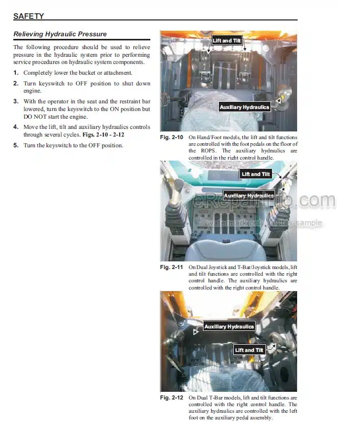
Relieving Hydraulic Pressure
Loader Lowering Procedure
-LUBRICATION
Hydraulic Oil Reservoir
Crankcase Oil
Chaincases
Grease Fitting Locations
Cooling System Drain Procedure
-MAINFRAME
Introduction
Mainframe (Chassis) – DPF Models
Mainframe (Chassis) – Non-DPF Models
Engine Access Cover – Removal and Installation
Roll-Over and Falling Object Protective Structure Components – ROPS/FOPS
ROPS FOPS Removal and Installation
Seat Removal and Installation
ROPS FOPS Rear Window Removal and Installation
Seat Slide Replacement
Restraint Bar Components
Restraint Bar Removal and Installation
Lift Ann Components – Gehl
Lift Arm Components – Mustang
All-TachS Hitch Components
All-TachS Hitch Removal and Installation
Lift Arm Removal and Installation
Lift Arm Bushing Replacement
Lift Arm Stop Installation and Adjustment
Mainframe Components – DPF Models
Mainframe Components – Non-DPF Models
Floor Covers and Kickplate Removal and Installation
Fuel Sensor Removal and Installation
Rear Grille Removal and Installation
Rear Grille Latch Removal and Installation
-WHEEL DRIVES
Introduction
Wheel Drive Components
Drive Chain Adjustment
Axle Housing Assembly Removal and Installation
Drive Chain Removal and Installation
Axle and Wheel Bearing Disassembly and Assembly
-CONTROLS
Introduction
Control Locations – T-Bar and Hand Foot
Wheel Drives Foot Throttle and Lift Tilt Components – T-Bar – DPF Models
Wheel Drives Foot Throttle and Lift Tilt Components – Parts Listing – T-Bar – DPF Models
Wheel Drives Foot Throttle and Lift Tilt Components – T-Bar – Non-DPF Models
Wheel Drives Foot Throttle and Lift Tilt Components – Parts Listing – T-Bar – Non-DPF Models
Wheel Drives Auxiliary Hydraulics and Lift Tilt Components – Hand Foot Models
Control Handle Removal and Installation
Control Handle Position Adjustment
Pivot Tube Weldment Removal and Installation – T-Bar
Neutral Centering Device and Pump Ann Removal and Installation
Neutral Centering Device Adjustment
Lift/Tilt Controls Removal and Installation
Lift/Tilt Control Adjustment
Auxiliary Hydraulics Cable Removal and Installation
Auxiliary Hydraulics Cable Adjustment
Electric Foot Throttle Pedal Removal and Installation – DPF Models
Handle Throttle Hand Throttle Cable and Throttle Rod Removal and Installation – Non-DPF Models
Foot Throttle and Foot Throttle Cable Removal and Installation – Non-DPF Models
Hand Throttle Adjustment – Non-DPF Models
Hand Throttle Tension Adjustment – Non-DPF Models
Foot Throttle Adjustment – Non-DPF Models
-HYDROSTATIC SYSTEM
Introduction
Hydrostatic Pump Assembly and Drive Motors
Hydrostatic Controls
Charge Pressure Test and Adjustment
Drive Motor Hot-Oil Shuttle Valve
Hydrostatic Pump Relief Valves
Hydrostatic Pump Removal / Installation
Hydrostatic Pump Flexible Drive Coupling Removal and Installation
Drive Motor Removal and Installation
Troubleshooting Guide
Hydrostatic Hydraulic Schematic – Gehl R105
Hydrostatic Hydraulic Schematic – Mustang 1050R
-HYDRAULIC SYSTEM
Introduction
Hydraulics – Self Level Valve Components
Hydraulics – Standard Auxiliary Components
Hydraulics – Lift Arm Components
Hydraulics – Chassis Components – DPF Models
Hydraulics – Chassis Components – Non-DPF Models
Pressure Tests Control Valve
Tilt Cylinder Test
Lift Cylinder Test
Self-Leveling Valve Test
Solenoid Valve Test – Tilt, Lift, Brake
Hydraulic Oil Filter Element Replacement
Hydraulics – Auxiliary
Tilt Cylinder Removal and Installation
Lift Cylinder Components
Tilt Cylinder Components
Lift Cylinder Removal and Installation
Lift/Tilt Cylinder Disassembly / Assembly
Gear Pump Removal and Installation
Self-Leveling Valve Removal and Installation
Self-Leveling Valve Adjustment
Safety Lock Valves – Removal/Installation
Lift Tilt and Brake Solenoid Valves – Disassembly and Assembly
Main Control Valve Components
Control Valve Removal and Installation
Main Relief Valve Removal and Installation
Troubleshooting Guide
-ELECTRICAL SYSTEM
Introduction
Description of Operation – Instrument Panel – DPF Models
Description of Operation – Instrument Panel – Non-DPF Models
Troubleshooting Guide
Electrical Chassis Components – DPF Models
Electrical Chassis Components – Non-DPF Models
Electrical ROPS FOPS Components – DPF Models
Electrical ROPS FOPS Components – Non-DPF Models
Power Distribution Module Test and Operation – DPF Models
Relay Test and Operation – Non-DPF Models
Interlock Control Module Test
Interlock Control Module Truth Table
Seats – Standard and Suspension
Restraint Bar Components
Restraint Bar Switch Removal and Installation
Seat Switch Removal and Installation
Electrical Lights Components
Front and Rear Work Light Bulb Replacement
Diesel Particulate Filter (DPF) Regeneration Procedures – DPF Models
Dome Light Bulb Replacement
Reset Regeneration
Reset Regeneration Inhibit
Stationary Regeneration
DPF Maintenance
Forcing Stationary Regeneration
Chassis Electrical Schematic – DPF Models
ROPS FOPS Electrical Schematic – DPF Models
Electrical Schematic – Non-DPF Models
-ENGINE
Introduction
Troubleshooting Guide
Engine Components and Engine Controls – DPF Models
Engine Components and Engine Controls – Non-DPF Models
Air Cleaner and Exhaust Components – DPF Models
Air Cleaner and Exhaust Components – Non-DPF Models
Radiator/Cooler Components – DPF Models
Radiator/Cooler Components – Non-DPF Models
Oil Filter Element Removal and Installation
Air Cleaner Assembly Removal and Installation
Air Filter Element Removal and Installation
Adding Fuel
Fuel Filter Removal and Installation
Water Separator Maintenance
Changing the Fuel Filter
Changing the Water Separator Filter
Electric Fuel Pump Removal and Installation
Priming the Diesel Fuel System
Battery Removal and Installation
Starter Removal and Installation
Exhaust Assembly Removal and Installation – Non-DPF Models
Exhaust Tube Removal and Installation – DPF Models
Fan Belt Adjustment
Radiator/ Oil Cooler Removal and Installation
Fan Shroud and Support Brackets Removal and Installation
Fan Shroud Adjustment
Fan Removal and Installation
Fuel Tank Removal
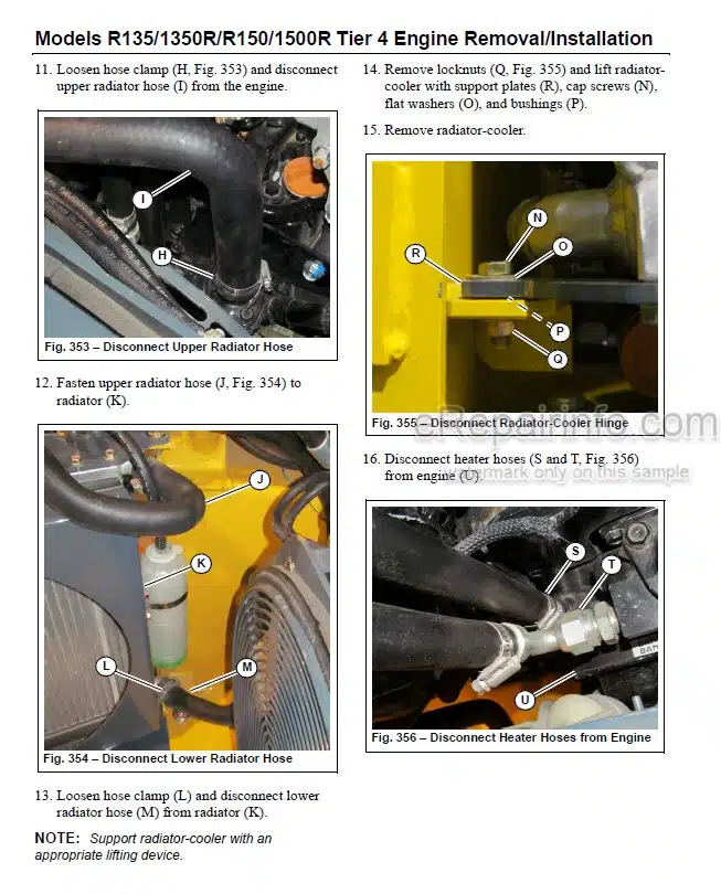
Engine Removal and Installation
Engine Diagnostic Chart (DPF Models)
Engine Diagnostic Trouble Codes (DTC)
Yanmar Engine Diagnostic Trouble Codes (DTC)
What you get
You will receive PDF file with high-quality manual on your email immediately after the payment.


Reviews
There are no reviews yet.