


Factory Service Manual For Gehl, Mustang And Manitou Compact Track Loader. Manual Contains Illustrations, Instructions, Diagrams For Step By Step Remove And Install, Assembly And Disassembly, Service, Inspection, Repair, Troubleshooting, Tune-Ups.
Format: PDF
Language: English
Pages: 278
Number: 50950470 (march 2020)
Bookmarks: Yes
Searchable: Yes
Wiring Diagrams: Yes
Hydraulic Diagrams: Yes
Model
Gehl, Mustang And Manitou Compact Track Loader
Gehl RT135
Gehl RT165
Manitou 1350RT
Manitou 1650RT
Mustang 1350RT
Mustang 1650RT
Contents
-SPECIFICATIONS!
Specifications
-SAFETY
Signal Words
Additional Safety Reminders
Mandatory Safety Shutdown Procedure
Lift Arm Support Device
Lift Arm Support Device Engagement
Lift Arm Support Device Disengagement
ROPS/FOPS – Raising
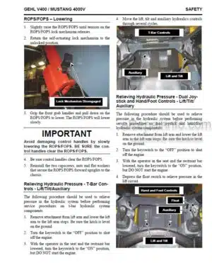
ROPS/FOPS – Lowering
Relieving Hydraulic Pressure – T-Bar Controls – Lift/Tilt/Auxiliary
Relieving Hydraulic Pressure – Dual Joystick, Dual Hand and Hand/Foot Controls – Lift/Tilt/Auxiliary
Loader Raising Procedure
Loader Lowering Procedure
-LUBRICATION
Hydraulic Oil Reservoir
Crankcase Oil
Grease Fitting Locations
Cooling System Drain Procedure
-CHASSIS
Mainframe (Chassis) Components
Grille and Engine Cover Components
Engine Access Cover – Removal and Installation
ROPS/FOPS
ROPS/FOPS Removal and Installation
Seat Removal and Installation
Seat Slide Replacement
Side Console Removal and Installation
Air Duct Louver Replacement
ROPS/FOPS Rear Window Removal and Installation
Restraint Bar Components
Restraint Bar Removal and Installation
All-Tach Hitch Components
Power-A-Tach Components
All-Tach and Power-A-Tach Hitch Removal and Installation
Lift Arm Components – RT165/1650RT Models
Lift Arm Components – RT135/135ORT Models
Lift Arm Removal and Installation
Lift Arm Bushing Replacement
Control Console Removal and Installation
Lift Ann Stop Installation and Adjustment
Clean-Out Cover, Floor Plate and Kickplate Cover Removal and Installation
Crossmember Removal and Installation
Fuel Sensor Removal and Installation
Rear Grille Removal and Installation
Rear Grille Latch Removal and Installation
-TRACK DRIVE
Track Drive Components
Tensioner Cylinder Components – RT135/1350RT Models
Tensioner Valve Components – RT135/1350RT Models
Track Tensioner Cylinder and Valve Components
Narrow Track Components – RT165/1650RT Models
Wide Track Components – RT165 and 165ORT Models
Rubber Track Removal and Installation
Pontoon Assembly Removal and Installation – RT165/1650RT Only
Travel Motor and Bogie Wheels Removal and Installation
Track Tensioner Adjustment Procedure
-CONTROLS
Control Locations – Dual Joystick and Hand/Foot Controls
Control Locations – T-Bar Controls
Track Drive – Lift/Tilt Components
Track Drive – Right Side Components – Dual Joystick Controls – RT135/135ORT Models
Control Handle Assembly (Both Control Handles) Removal and Installation
Control Handle Removal and Installation
T-Bar Control Handle Assembly
Dual Joystick Control Handle Assembly
Hand/Foot Control Handle Assembly
Pivot Tube Removal and Installation, Disassembly and Assembly – T-Bar and Hand/Foot Controls
Control Handle Position Adjustment – T-Bar and Hand/Foot Controls
Control Handle Tracking Adjustment
Neutral Centering Test and Adjustment
Lift/Tilt Control Removal and Installation
Electrical Foot Throttle Removal and Installation – (Option)
Lift/Tilt Control Adjustment – T-Bar and Hand/Foot Controls
Electrical Foot Throttle Components
-HYDROSTATIC SYSTEM
Hydrostatic Components
Right Hydrostatic Components – Dual Joystick Controls – Models RT135/1350RT
Hydrostatic Components – Track Tension Circuit – Models RT135/1350RT
Charge Pressure Test and Adjustment
Hydrostatic Pump Relief Valves
Hydrostatic Pump Removal and Installation
Hydrostatic Pump Drive Coupling Removal and Installation
Troubleshooting Guide
Hydrostatic/Hydraulic Schematic
-HYDRAULIC SYSTEM
Hydraulics – Hydraglide
Hydraulics – Standard Auxiliary Components
Hydraulics – High-Flow Auxiliary Components
Hydraulics – Self-Leveling Components
Hydraulics – Non-Self-Leveling Components
Hydraulics – Standard Auxiliary Lift Ann Components – Models RT165/1650RT
Hydraulics – Lift Ann Components – Models RT135/1350RT
Hydraulics – High-Flow Auxiliary Lift Ann Components – Models RT165/1650RT
Hydraulics – Chassis Components
Hydraulics – Lift Ann Power-A-Tach Components
Hydraulics – Power-A-Tach Components – High-Flow Auxiliary
Pressure Check, Test and Adjustment
Tilt Cylinder Test
Tilt Circuit Spool Leakage Test
Self-Leveling Valve Test
Lift Cylinder Test
Lift Circuit Spool Leakage Test
Solenoid Valve Test – Lift Ann Pilot Supply Joystick Drive Supply Power-A-Tach Brake/Two-Speed, Safety Locks and Ride Control
Lift Cylinder Components
Tilt Cylinder Components
Hydraulic Oil Filter Element Replacement
Tilt Cylinder Removal and Installation
Lift Cylinder Removal and Installation
Auxiliary’ Pump Removal and Installation
Self-Leveling Valve (Optional) Removal and Installation
Self-Leveling Valve Adjustment
Brake Two-Speed, Lift Ann Pilot Supply and Safety Lock Solenoid Valves – Removal and Installation
Joystick Drive Supply Power-A-Tach and Hydraglide Ride Control
Solenoid Valves – Removal and Installation
Lift Tilt, Joystick Drive Supply Brake/Two-Speed, All-Tach/Fan and Hydraglide Ride Control Solenoid Valves – Disassembly and Assembly
Control Valve Removal and Installation
Main Control Valve Components – Standard
Main Control Valve Components – High-Flow
Control Valve Disassembly and Assembly
Control Valve Solenoid Removal and Installation
Inlet Relief Valve, Port Relief Valve and High-Flow Relief Valve Removal and Installation
Hydraglide Ride Control Accumulator Removal and Installation
-ELECTRICAL SYSTEM
Description of Operation – Operator Safety Interlock
Right Instrument Panel – Control Keypad Indicators
Right Instrument Panel – Control Keypad Buttons
Right Instrument Panel – Information Center Electronic Display
Information Center Electronic Display Symbols
Information Center Electronic Display Screens
Left Instrument Panel
Troubleshooting Guide – Electrical System
Electrical Chassis Components
Electrical Fuses and Relays Components
Electrical ROPS/FOPS Components
Power Distribution Module Test and Operation
Electrically-Controlled Standard Auxiliary Hydraulic Flow System Test and Operation
Engine Throttle Test and Operation
Seat Switch Removal and Installation
Restraint Bar Switch Removal and Installation
Master Disconnect Switch – Remote Battery’ Terminal Removal and Installation
Dome Light Bulb Replacement
Front and Rear Work Light Bulb Replacement
Control Handle Actuation Buttons – Two-Speed and Ride Control and Float Module
Restraint Bar Components
DPF (Diesel Particulate Filter) Regeneration
Electrical Chassis Schematic,
Electrical ROPS/FOPS Schematic
Electrical ROPS/FOPS Schematic, Page 3 of 3
Electrical Engine Schematic, DPF Engine
Electrical Engine Schematic, Non-DPF Engine
Electrical Road Lights Schematic
Electrical HVAC Schematic
Electrical Track Tension Schematic
-ENGINE
Troubleshooting Guide
Engine Components (DPF)
Engine Components (Non DPF)
Air Intake Components
Radiator/Cooler Components
Oil Filter Element Removal and Installation
Air Cleaner Assembly Removal and Installation
Air Filter Element Removal and Installation
Battery Removal and Installation
Starter Removal and Installation
Alternator Belt Adjustment
Exhaust Pipe Removal and Installation
Radiator/Cooler Removal and Installation
Fan Shroud and Mounting Plates Removal and Installation
Fan Adjustment
Fan Removal and Installation
Engine Removal and Installation
Engine Diagnostic Data Port
Yanmar Engine Diagnostic Fault Codes
What you get
You will receive PDF file with high-quality manual on your email immediately after the payment.


Reviews
There are no reviews yet.