


Factory Technical Manual and Workshop Manual For Hitachi EX300-5, EX300LC-5, EX330LC-5, EX350H-5, EX350LCH-5, EX370-5, EX370HD-5 Excavators. Tons of illustrations, instructions, diagrams for step by step remove and install, assembly and disassembly, service, inspection, repair, troubleshooting, tune-ups.
Format: PDF
Language: English
Bookmarks: Yes
Searchable: Yes
Wiring Diagrams: Yes
Hydraulic Diagrams: Yes
Model
Hitachi EX300-5, EX300LC-5, EX330LC-5, EX350H-5, EX350LCH-5, EX370-5, EX370HD-5
Contents
1.Technical Manual
–SPECIFICATION
Specifications
Working Ranges and Machine
Dimensions for Transportation
Component Specifications
–COMPONENT LAYOUT
Main Components
Electrical System (Overall System)
Electrical System (Relays)
Electrical System (Monitor and Switch Panels)
Other Components
-SYSTEM
–CONTROL SYSTEM
Outline
Engine Control
Pump Control
Valve Control
Other Control Functions
–HYDRAULIC SYSTEM
Main Circuit
Pilot Circuit
Neutral Circuit
Single Actuator Operation
Combined Operation
–ELECTRICAL SYSTEM
Outline
(Key Switch OFF Position)
Bulb Check Circuit (Key Switch ON Position)
Accessory Circuit
Preheat Circuit (Key Switch ON or START Position)
Starting Circuit (Key Switch START Position)
Charging Circuit (Key Switch ON Position)
Surge Voltage Prevention Circuit
Engine Stop Circuit
-COMPONENT OPERATION
–PUMP DEVICE
Outline
Main Pump
Regulator
Pilot Pump
N Sensor (Engine Speed Sensor)
Pump Delivery Pressure Sensor
–SWING DEVICE
Outline
Swing Motor
Swing Parking Brake
Valve Unit
Swing Reduction Gear
–CONTROL VALVE
Outline
Hydraulic Circuit
Flow Combiner Valve
Pump Control Valve
Main Relief Valve
Overload Relief Valve
Arm Regenerative Valve
Boom Regenerative Valve
Arm Anti-Drift Valve (Bottom Side)
Arm Anti-Drift Valve (On Rod Side) / Boom Anti-Drift Valve
Bucket Flow Rate Control Valve
Travel Flow Rate Control Valve
Bypass Shut-Out Valve
Needle Valve
–PILOT VALVE
Outline
Operation
–TRAVEL DEVICE
Outline
Travel Motor
Parking Brake
Travel Speed Control
Travel Brake Valve
Travel Reduction Gear
–OTHERS (UPPERSTRUCTURE)
Pilot Shut-Off Valve
Shockless Valve
Solenoid Valve Unit
Pilot Relief Valve
EC Motor
–OTHERS (UNDERCARRIAGE)
Swing Bearing
Center Joint
Track Adjuster
-OPERATIONAL PERFORMANCE TEST
–INTRODUCTION
Operational Performance Tests
Preparation for Performance Tests
–ENGINE TEST
Engine Speed
Engine Compression Pressure
Valve Clearance Adjustment
Nozzle Check
Injection Timing
–EXCAVATOR TEST
Travel Speed
Track Revolution Speed
Mistrack Check
Travel Parking Function Check
Swing Speed
Swing Function Drift Check
Swing Motor Leakage
Swing Bearing Play
Maximum Swingable Slant Angle
Hydraulic Cylinder Cycle Time
Dig Function Drift Check
Control Lever Operating Force
Control Lever Stroke
Combined Boom Raise/Swing Function Check
–COMPONENT TEST
Primary Pilot Pressure
Secondary Pilot Pressure
Solenoid Valve Set Pressure
Main Relief Valve Set Pressure
Overload Relief Valve Set Pressure
Main Pump Flow Rate
Swing Motor Drainage
Travel Motor Drainage
–STANDARD
Operational Performance Standard Table
Main Pump P-Q Curve
Injection Pump
-TROUBLESHOOTING
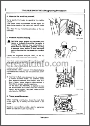
–DIAGNOSING PROCEDURE
Introduction
Diagnosing Procedure
DrEX
DrEX Start-Up Procedure
Fault Code
DrEX Monitoring Function
DrEX Special Function (Service Mode)
Controllable Data
–COMPONENT LAYOUT
Main Components
Electrical System (Overall System)
Electrical System (Relays)
Electrical System (Monitor and Switch Panels)
Other Components
–TROUBLESHOOTING A
Troubleshooting A Procedure
Fault Code
Fault Code 01
Fault Code 02, 03
Fault Code 04, 05
Fault Code 06
Fault Code 07
Sensor Operating Range List
–TROUBLESHOOTING B
Troubleshooting B Procedure
Relationship between Machine Trouble Symptoms and Parts in Trouble
Correlation between Trouble Symptoms and Part Failures
Engine Troubleshooting
Overall Actuator System Troubleshooting
Front Attachment Control System Troubleshooting
Swing System Troubleshooting
Travel System Troubleshooting
Troubleshooting for Other Functions
Engine Speed Adjustment and Engine Learning
Exchange Inspection Method
Boom Lowering Method when Engine Stalls
–TROUBLESHOOTING C
Troubleshooting C Procedure
Malfunction of Coolant Temperature Gauge
Malfunction of Fuel Gauge
Malfunction of Indicator Light Check System
Malfunction of Level Check Switch
Malfunction of Preheat Indicator
Malfunction of Engine Oil Level Indicator
Malfunction of Coolant Level Indicator
Malfunction of Hydraulic Oil Level Indicator
Malfunction of Alternator Indicator
Malfunction of Engine Oil Pressure Indicator
Malfunction of Overheat Indicator
Malfunction of Fuel Level Indicator
Malfunction of Air Filter Restriction Indicator
Malfunction of Buzzer
Malfunction of Hour Meter
–ELECTRICAL SYSTEM INSPECTION
Precautions for Inspection and Maintenance
Instructions for Disconnecting Connectors
Fuse Continuity Test
Inspection and Replacement of Fusible Links
Battery Voltage Check
How to Troubleshoot Alternator Malfunctions
Continuity Check
Voltage and Current Check
Replacement of Relay
–HARNESS CHECK
Circuit Check
2.Workshop Manual
INTRODUCTION
SAFETY
-GENERAL INFORMATION
–PRECAUTIONS FOR DISASSEMBLY AND ASSEMBLY
Precautions for Disassembly and Assembly
–TIGHTENING TORQUE
Tightening Torque Specification
Torque Chart
Piping Joint
-UPPERSTRUCTURE
–CAB
Remove and Install Cab
Dimensions of the Cab Glass
–COUNTERWEIGHT
Remove and install Counterweight
–MAIN FRAME
Remove and Install Main Frame
–PUMP DEVICE
Remove and Install Pump Device
Disassemble Pump Device
Assemble Pump Device
Disassemble Main Pump
Assemble Main Pump
Disassemble Regulator
Assemble Regulator
Disassemble and Assemble Pilot Pump
Maintenance Standard
–CONTROL VALVE
Remove and Install Control Valve
Disassemble Control Valve
Assemble Control Valve
–SWING DEVICE
Remove and Install Swing Device
Disassemble Swing Device
Assemble Swing Device
Disassemble Swing Motor
Assemble Swing Motor
Disassemble and Assamble Release Valve
Maintenance Standard
–CONTROL VALVE
Remove and Install Control Valve
Disassemble Control Valve
Assemble Control Valve
–SWING DEVICE
Remove and Install Swing Device
Disassemble Swing Device
Assemble Swing Device
Disassemble Swing Motor
Assemble Swing Motor
Disassemble and Assamble Release Valve
Maintenance Standard
–PILOT VALVE
Remove and Install Right Pilot Valve
Remove and Install Left Pilot Valve
Remove and Install Travel Pilot Valve
Disassemble Right and Left Pilot Valve
Assemble Right and Pilot Valve
Disassemble Travel Pilot Valve
Assemble Travel Pilot Valve
–PILOT SHUT-OFF VALVE
Remove and Install Pilot Shut-off Valve
Disassemble Pilot Shut-off Valve
Assemble Pilot Shut-off Valve
–SHOCKLESS VALVE
Remove and Install Shockless Valve
Disassemble and Assemble Shockless Valve
–SOLENOID VALVE
Remove and Install Solenoid Valve Unit
Disassemble Propotional Solenoid Valve
Assemble Propotional Solenoid Valve
–PILOT RELIEF VALVE UNIT
Remove and Install Pilot Relief Valve Unit
Disassemble Pilot Relief Valve
Assemble Pilot Relief Valve
-UNDERCARRIAGE
–SWING BEARING
Remove and Install Swing Bearing
Disassemble Swing Bearing
Assemble Swing Bearing
–TRAVEL DEVICE (EX300-5, EX350H-5)
Remove and Install Travel Device
Disassemble Travel Device
Assemble Travel Device
Disassemble Travel Motor
Assemble Travel Motor
Disassemble Brake Valve
Assemble Brake Valve
Maintenance Standard
(EX370HD-5)
Remove and Install Travel Device Disassemble Travel Device
Assemble Travel Device
Disassemble Travel Motor
Assemble Travel Motor
Disassemble Brake Valve
Assemble Brake Valve
Maintenance Standard
–CENTER JOINT
Remove and Install Center Joint
Disassemble Center Joint
Assemble Center Joint
Maintenance Standard
–TRACK ADJUSTER (EX300-5, EX350H-5)
Remove and Install Track Adjuster
Disassemble Track Adjuster
Assemble Track Adjuster
(EX370HD-5)
Remove and Install Track Adjuster
Disassemble Track Adjusteri
Assemble Track Adjuster
–FRONT IDLER
Remove and Install Front Idler
Disassemble Front Idler
Assemble Front Idler
Maintenance Standard1
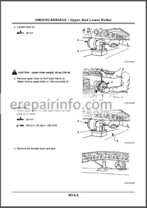
Group 6 Upper and Lower Roller
Remove and Install Upper Roller
Remove and Install Lower Roller
Disassemble Upper Roller
{EX370HD-5}
Assemble Upper Roller (EX370HD-5)
Disassemble Lower Roller
Assemble Lower Roller
Maintenance Standard
–TRACK
Remove and Install Track
Maintenance Standard
-FRONT ATTACHMENT
–FRONT ATTACHMENT
Remove and Install
Front Attachment
Maintenance Standard
Standard Dimensions for Arm and Bucket Connection
–CYLINDER
Remove and Install Cylinder
Hydraulic Circuit Pressure Release Procedure
Cylinder Air Bleeding Procedure
Disassemble Cylinder
Assemble Cylinder
Maintenance Standard
-ENGINE
–GENERAL INFORMATION
General servicing precautions
Notes on the Format of this Manual
About Angular Tightening
Main Data and Specifications
Performance Curve
External View
Tightening Torque Specifications
Tightening Torque for Main Parts
Model and Identification Serial Number
–MAINTENANCE
Lubricating System
Fuel System
Cooling System
Valve Clearance Adjustment
Fuel Injection Timing
Recommended Lubricating Oil
Cylinder Compression Pressure
Engine Repair Kit
–ENGINE I (DISASSEMBLY)
External View
Disassembly 1
Disassembly 2
Disassembly 3
Cylinder Head Disassembly
Rocker Arm Shaft Disassembly
Piston and Connecting Rod Disassembly
–ENGINE II (INSPECTION AND REPAIR)
Inspection and repair (1)
Cylinder Head
Valve Guide
Valve and Valve Seat Insert
Valve Spring
Rocker Arm Shaft and Rocker Arm
Camshaft
Inspection and repair (2)
Cylinder Block, Cylinder Liner Piston
Piston Ring
Piston Pin
Connecting Rod
Crankshaft
Crankshaft and Bearing
Front Cover Oil Seal
Crankshaft Rear Oil Seal
–ENGINE III (ASSEMBLY)
Rocker Arm Shaft Assembly
Cylinder Head Assembly
Piston and Connecting Rod Assembly
Assembly 1
Assembly 2
Assembly 3
Timing Gear Train Diagram
–LUBRICATION SYSTEM
Introduction
Oil Pump
Oil Filter
Oil Cooler
–COOLING SYSTEM
Introduction
Water Pump
Thermostat
–FUEL SISTEM
Introduction
Nozzle Holder Assembly
–TURBOCHARGER
Inspection And Repairs
–ENGINE ELECTRIAL
Starter
Main Data and Specifications
Sectional Diagram
Performance Characteristics
Disassembly
Inspection 3nd Pep3ir
Assembly
Alternator
Main Data and Specifications
Secional Diagram
Performance Characteristics
Circuit Diagram
Disassembly
Inspection And Repair
Assembly
–TROUBLESHOOTING
STARTING DIFFICULTIES
STARTER DOESN’T TURN
STARTER TURNS, BUT ENGINE DOESN’T TURN OVER
THE ENGINE TURNS AND FUEL REACHES THE INJECTION PUMP, BUT IT DOESN’T START
THE ENGINE TURNS, BUT DOES NOT START
FUEL ISN’T SUPPLIED TO THE INJECTION PUMP
Unstable Idling rpm
Lack of Power
Excessive Fuel Consumption
Excessive Oil Consumption
Overheating
White Smoke in Exhaust
Black Smoke in Exhaust
Low Oil pressure
Engine Sounds
KNOCKING
GAS LEAK SOUNDS
CONTINUOUS SOUNDS
CLANKING SOUNDS
–SPECIAL TOOL
Special Tool List
–REPAIR STANDARDS
General Rules
Repair Standards
What you get
You will receive PDF file with high-quality manual on your email immediately after the payment.


Reviews
There are no reviews yet.