


Factory Service Manual For JCB Side Engine Loadall Telescopic Handler. Manual Contains Illustrations, Instructions, Diagrams For Step By Step Remove And Install, Assembly And Disassembly, Service, Inspection, Repair, Troubleshooting, Tune-Ups.
Format: PDF
Language: English
Pages: 2187
Number: 9813/0950-5 (issued 2004)
Searchable: Yes
Wiring Diagrams: Yes
Hydraulic Diagrams: Yes
Model
JCB Side Engine Loadall Telescopic Handler
540-140
540-200
Serial No. TBA
540-170
Serial No. from 1522578 to TBA
535-125 Hi Viz
Serial No. from 1522579 to TBA
535-140 Hi Viz
Serial No. from 1522591 to TBA
Contents
-GENERAL INFORMATION
Applications
Use
Machine Identification
Torque Settings
Service Tools
Service Consumables
Fuel
Stall Speed Combinations
-CARE AND SAFETY
Safety Notices
General Procedures
-ROUTINE MAINTENANCE
Applications
Routine Maintenance
-BODY AND FRAMEWORK
Applications
Fork Carriage
Cab Heating and Ventilation System
Cab Air Conditioning System
Longitudinal Load Moment System
Cab
Air Conditioning Condenser – Cooling Pack Mounted
Air Conditioning Condenser – Cab Roof Mounted
Cab HV and HVAC Unit
Air Conditioning Binary Switch
Heater Valve
Fuel Tank
Engine Cover
Valve Block Covers
Mudguards
Chaff Guards
Deckplate
Boom
LLMI Axle Transducer
Stabilisers
Longitudinal Load Moment Indicator Unit
Longitudinal Load Moment Control Sensors
Cab Side Cover
-ELECTRICS
Applications
Fuses and Relays
Schematics
Electrical Harness System
Battery Charging System
Alternator
Battery
-HYDRAULICS
Applications
Systems and Schematics
Parallel Hydraulic System
Parallel Servo Hydraulic System
LSP Electro Servo Hydraulic System
Hydraulic Interlock System
Auxiliary Relief Valve (ARV) Operation
Main Relief Valve (MRV)/Load Sense Relief Valve (LSRV) Operation
Pressure Compensator Operation
Parallel Lift Operation
Parallel Circuit Operation
Parallel Servo Circuit Operation
LSP Circuit Operation
Boom Pressure Balance System
Universal Hydraulic Circuit Faults
Parallel Circuit Faults
Parallel Servo Circuit Faults
LSP Electro Servo Circuit Faults
Parallel System Pressure Tests
Pump Flow Tests – Gearpump
Parallel Servo System Pressure Tests
LSP System Pressure Tests
Parallel Control Valve
Electro Servo Control Valve
Servo Solenoid Diverter Valve Block
Gearpump Operation
Gearpump Removal and Replacement
Hydraulic Cooling Fan Motor – Fixed Speed
Servo Control Valves
Electro Servo Control Lever
Electrical Stabiliser Control Levers
Stabiliser Isolation Valve
Stabiliser Ram
Sway Ram
Displacement Ram
Tilt Ram
Lift Rams
Extension Ram
Ram Maintenance
Sway/Fan Selector Valve
Hydraulic Oil Cooler By-Pass System
Hydraulic Oil Cooler By-Pass Valve
Sway Circuit – Bleed Procedure
Tilt Circuit – Bleed Procedure
3 Stage Boom – Extend Circuit – Bleed Procedure
4 Stage Boom – Extend Circuit – Bleed Procedure
-TRANSMISSION
Applications
Configuration
Wheels and Tyres
Front Axles
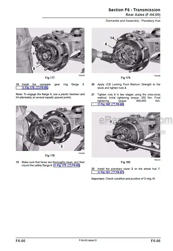
Rear Axles
PS750 Mk IV Gearbox System
PS764 Gearbox System
PS750 Mk IV Hydraulic Operation
PS760 Gearbox Hydraulic Operation
Gearbox Systems Fault Finding
PS750 Mk IV Gearbox – Hydraulic Testing
PS760 Gearbox – Hydraulic Testing
Torque Converter Stall Tests
Flushing the Transmission Oil
PS750 Mk IV Gearbox
PS760 Gearbox
Torque Converter Operation
Torque Converter
Bevel Gearbox
Transmission Oil Cooler – Air Blast
Transmission Oil Cooler – Liquid to Liquid
Propshafts
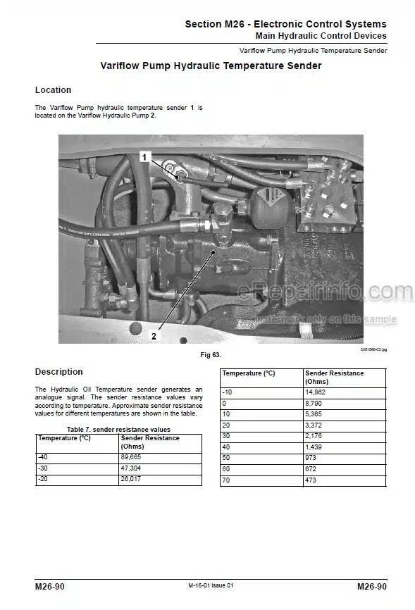
Transmission Speed Sensor
Speed Sensors
Engine Speed Sensor
-BRAKES
Applications
Twin Axle Service Brakes System
External Park Brake System
Internal Park Brake System
Park Brake Calliper
Park Brake Disc
Park Brake Switch
Servo Exhauster Unit
Servo Unit, Twin Axle Brakes
Master Cylinder
Fluid Reservoir
-STEERING
Applications
Steering System
Manual Steer Mode System
Auto Steer Mode System
Hydraulic Steering Unit
Priority Valve
Power Track Rod
Steer Rams
Steering Column
Manual Steer Mode Valve
Auto Steer Mode Valve
Steer Proximity Switches
-ENGINE
Applications
Start and Stop System
Cold Start Heater System
Starter Motor
Cooling Pack
Coolant Expansion Tank
Air Filter Vacuum Switch
Throttle Pedal and Cable
Throttle Position Sensor
Exhaust Silencer
JCB Dieselmax
-ELECTRONIC DATA SYSTEMS
Applications
CANbus System
Loadall Monitoring System
Fault Code System
Servicemaster System
Servicemaster Tool Set
JCB DieselMax 4.4L Tier 3 SE) Diagnostic Tool – User Guide
JCB DieselMax (4.4L Tier 3 SE) Engine Setup Tool – User Guide
Cluster (LMS) Setup Tool – User Guide
Loadall Datalogger Tool – User Guide
Loadall Machine Diagnostics Tool – User Guide
Boom Angle Sensor Calibration Tool – User Guide
Immobiliser Diagnostics Tool
Immobiliser Setup Tool
Pulse Width Modulation Theory
Electronic Control Unit Theory
Livelink ECU
Immobiliser ECU
Hydraulic Control ECU
What you get
You will receive PDF file with high-quality manual on your email immediately after the payment.


Reviews
There are no reviews yet