


Factory Service And Maintenance Manual For JLG Compact Crawler Boom. Manual Contains Important Information And Instructions For Maintenance Description Of The Functions And Capabilities Of The System. Illustrations, Instructions, Diagrams For Step By Step Remove And Install, Assembly And Disassembly, Service, Inspection, Repair, Troubleshooting, Tune-Ups.
Format: PDF
Language: English
Pages: 633
Issue: june 2012
Searchable: Yes
Wiring Diagrams: Yes
Hydraulic Diagrams: Yes
Model
JLG Compact Crawler Boom
X14JH
X14J
X390AJ
X17J
X19J
X550AJ
X23J
X700AJ
Contents
-INTRODUCTION – MAINTENANCE SAFETY PRECAUTIONS
General
Hydraulic System Safety
Maintenance
-SPECIFICATIONS
Capacities
Tracks
Engine Data
Specifications and Performance Data
Function Speeds
Pressure Settings – PSI (Bar)
Serial Number Location
-GENERAL
Machine Preparation, Inspection, and Maintenance
Service and Guidelines
Lubrication and Information
Cylinder Drift Test
Pins and Composite Bearing Repair Guidelines
Welding on JLG Equipment
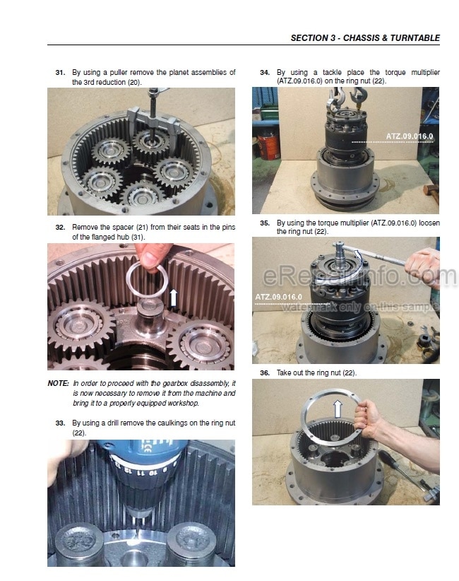
-CHASSIS & TURNTABLE
Rubber Track Maintenance
Undercarriage Components
Cylinders And Enlargement Guide
Drive Gear Motor Table
Track Drive – Bonfiglioli
Drive Hub – Eaton
Swing Drive (IMO)
Honda Engine GX270 – GX390
Honda Engine IGX440
Hatz Engine
Perkins Engine
Engine Removal
Changing The Electric Motor
-BOOM & PLATFORM
Boom Maintenance
Boom Disassembly X23J – X700AJ
Inspection
Ropes Tension Adjustment Procedure
Rotary Actuator
Platform Removal/Installation
Load Cell And Footswitch Removal/Installation
-HYDRAULICS
Cylinder Repair
Replacement Hydraulic Pump
Function Pump
Hydraulic Component Start-Up Procedures And Recommendations
Pressure Setting Procedure
Hydraulic Schematic
-JLG CONTROL SYSTEM
Introduction
Platform/Remote Control Station LCD Display
Canbus Communications
Calibration Instructions
Platform Remote Control Service
Menu Input
Language
Menu Errors
Ramps
Currents
Working Hours
Machine Setup
Joystick
Calibrating Joystick
Configuration Serial Number Radio Remote Control (X17J Only)
-BASIC ELECTRICAL INFORMATION & SCHEMATICS
Description For Models X14J/X390Aj-X19J/X550Aj-X23J/X700Aj
A-How to Read The Wiring Diagrams
B – Photocells – Safety Exclusion – Slew Proximity- Stabilizers Pressure Sensors
C – Aerial Part Safety Chain: Outriggers Aligned Switches (Only X23J-X700Aj)
D – Aerial Part Safety Chain: Outriggers Switches
E – Can Network – Cylinders Position Sensors – Remote Control Connector- Modem
F – Ropes Switch – Jib Position Switch – Pedal – Load Cell
G- Engine Stop Switches-Engine Start Push Buttons (Ground)-Aerial Movements Abilitation Switch (Ground)
H – Emergency Descend Electro Valves – Optionals
I – Electric Power Supply
L – Ground Part: Tracks – Undercarriage Widening – 2° Speed – Proportional Electro Valves
M – Ground Part: Outriggers – Electric Diverter
N – Aerial Part: Basket Levelling – Basket Rotation – Jib – Proportional Electro Valve
0 – Aerial Part: 1° Cylinder – 2° Cylinder – Extension – Rotation
P1 – Thermic Engine Connexion (Gasoline) – X19J-X550Aj/X23J-X700Aj
P2 – Thermic Engine Connexion (Diesel) – Diesel Engine Sensors – X23J-X700Aj
P3 – Thermic Engine Connexion (Diesel) – X14J-X390Aj/X19J-X550Aj
P4 – Thermic Engine Connexion (Gasoline) – X14J-X390Aj
Q – 110-220 Volt Electric Power Supply – Electric Engine
R – Double Stabilization Area With Rotation Sensor – X23J-X700Aj
Description For Models X14Jh – X17J
A – How To Read The Wiring Diagrams
B – Photocells – Safety Exclusion – Slew Proximity – Stabilizers Pressure Sensors-1’arm Switch
C – Aerial Part Safety Chain: Outriggers Switches
D – Can Network – Jib Position Switch – Modem
E – Handle Switches – Load Cell – Pedal
F – Engine Stop Switches – Engine Start Push Buttons (Ground) – Aerial Movements Abilitation Switch (Ground)
G – Emergency Descend Electro Valves – Remote Control Battery Charger – Optionals
H – Electric Power Supply
1 – Ground Part: Tracks – Undercarriage Widening – 2S Speed – Proportional Electro Valves
L – Ground Part: Outriggers – Electric Diverter – Aerial Safety Electro Valve
M1 – Thermic Engine Connexion (Gasoline)
M2 – Thermic Engine Connexion (Diesel)
N – 220 Volt Electric Power Supply – Electric Engine
Electric Schedules Layout
Components Location
Z1 – Battery Pack And BMS
Z2 – Relais – Fuses – 12V Battery
Z3 – Can Bus Line – Main Switch – Ignition Key
Z4 – Inverter – Motor – ECM
What you get
You will receive PDF file with high-quality manual on your email immediately after the payment.


Reviews
There are no reviews yet.