Factory Technical Manual For John Deere Loader. Manual Contains Illustrations, Instructions, Diagrams For Step By Step Remove And Install, Assembly And Disassembly, Service, Inspection, Repair, Troubleshooting, Tune-Ups.
Format: PDF
Language: English
Pages: 304
Number: SP2254REN
Hydraulic Diagrams: Yes
Model
John Deere Comeco Loader
2254
Contents
-SAFETY RECOMMENDATIONS
Safety and You
Operation Safety
Service Safety
Safety in Your Service Area
Safety when Cleaning or Storing
Safety Nevers
Recognize Safety Information
Understand Signal Words
Follow Safety Instructions
Protect Bystanders
Use Handles and Steps
Prevent Machine Runaway
Avoid Exhaust Fumes
Keep Riders off Machine
Handle Fuel Safely—Avoid Fires
No Hands Through Steering Wheel
Safely Service Cooling System
Prepare For Emergencies
Wear Protective Clothing
Use Safety Lights and Devices
Practice Safe Maintenance
Avoid High Pressure Fluids
Use Caution on Hillsides
Stopping and Parking
Service Tires Safely
Avoid Electrical Power Lines
Avoid Contact with Moving Parts
Dispose of Waste Properly
Fire Prevention
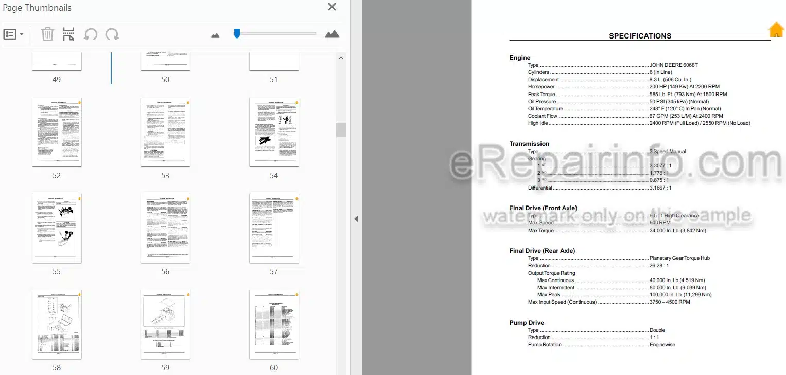
-SPECIFICATIONS
Engine
Transmission
Final Drive (Front Axle)
Final Drive (Rear Axle)
Pump Drive
Double Vane Pump
Single Vane Pump
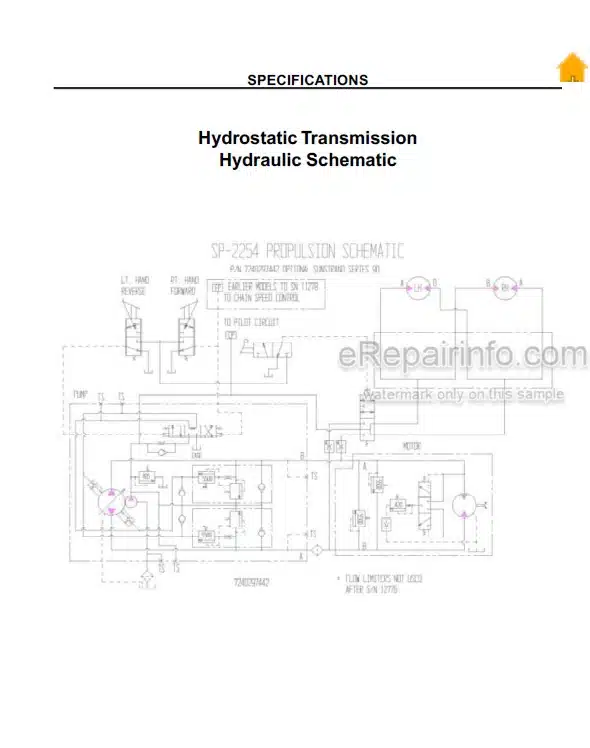
Variable Displacement Pump (Hydrostatic Transmission)
Variable Displacement Motor (Rear Axle)
Fixed Displacement Motor (Front Axle)
Steering Cylinders
Swing Cylinders
Flex Cylinder
Piler Lift Cylinders
Piler Motor Circuit
Grab Cylinders
Lift Cylinder
Loading System
Control Valve—Boom Lift and Grab
Traction System
Front Axle Motor
Steering System
Piler Chain System
Grab and Lift Schematic
Steer, Swing Flex and Piler Lift Schematic
-CAPACITIES
Engine
Radiator
Transmission
Rear Steering Axle
Front Rigid Axle
Brake Fluid
Hydraulic Tank
Fuel Tank
Torques (Dry)
Tire Inflation Pressure
Pump Drive
-TORQUE SPECIFICATIONS
Torque for SAE Bolts and Nuts in LB-FT
Torque for SAE Bolts and Nuts in NM
Torque for Grade 2 NC Weld Studs
Conversion Factors
Torque for SI (Metric) Bolts and Nuts in NM
Grade or Property Class Head
Marking for SI Bolts
Conversions
Weight Measure
Length Measure
Metric Measurements
Metric to English
English to Metric
Muliplication Factors
Temperature Conversion Chart
Conversion Formulas
-FLUID RECOMMENDATIONS
Engine Coolant Requirements
Antifreeze
Water
Inhibitors (Conditioners)
Filling the System
Ambient Temperature Chart
Sulphur Content
Specifications
Cetane
Cloud Point
Storage And Handling
Hydraulic Oil Chart
Hydraulic Fluid
Gear Oil – Final Drive
Engine Oil
Gear Oil – Pump Drive (if equipped)
Grease
-GENERAL INFORMATION
Introduction
Diagnostic Sections
Troubleshooting Tools
Troubleshooting
Visually Inspect Hydraulic Systems
Hydraulic System Testing Precautions
Visually Inspect Electrical System
Electrical System Safety Precautions
Service Supplies
Service Tools
For Complete Kit Order 0600044329
For Flow Meter Test Kit Order 0601305130
For Optional Tester Hose
Kit Order 0840317083
Tool Set—Mechanics
-SERVICE POINTS
Initial Start-Up
First 50 Hours of Operation
Every 10 Hours or Daily Operation
Start Engine
Every 70 Hours of Operation
Every 140 Hours – 2 Weeks of Operation
Every 250 Hours – Monthly Operation
Every 500 Hours – 2 Months of Operation
Every 1000 Hours —4 months of Operation
As Necessary
-HYDROSTATIC SYSTEM
The System Circuit
The Basic Closed Circuit
Case Drain and Heat Exchanger
General Description and Cross Sectional Views
Variable Displacement Pumps
Fixed Displacement Motor
Charge Pump
Charge Relief Valve
System Check Valves
PV with Charge Pump
Charge Pump Components
Pump Charge System
Multi-Function Valves
Pressure Limiter and High Pressure Relief Valves
Bypass Valves
PV Showing Location of Multi-Function Valves
Cross Section of Multi-Function Valve
Circuit Diagram Showing Pressure Control Mechanisms
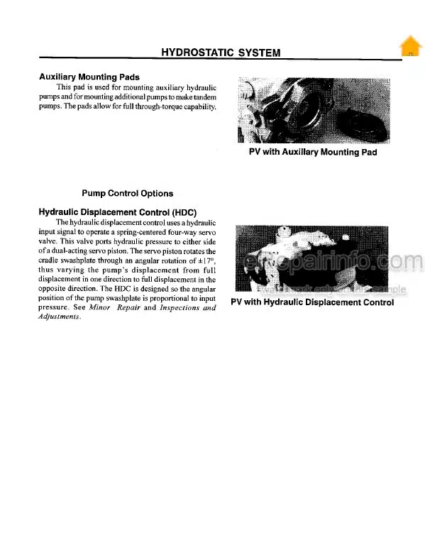
Auxiliary Mounting Pads
Pump Control Options
Hydraulic Displacement Control (HOC)
PV with Auxiliary Mounting Pad
PV with Hydraulic Displacement Control
Initial Start-Up Procedure
Fluid and Filter Maintenance
System Operation Hot
Neutral Difficult or Impossible to Find
Trans Only Operates in One Direction
System Will Not Operate in Either Direction
Low Motor Output Torque
Improper Motor Output Speed
Excessive Noise and Vibration
System Response is Sluggish
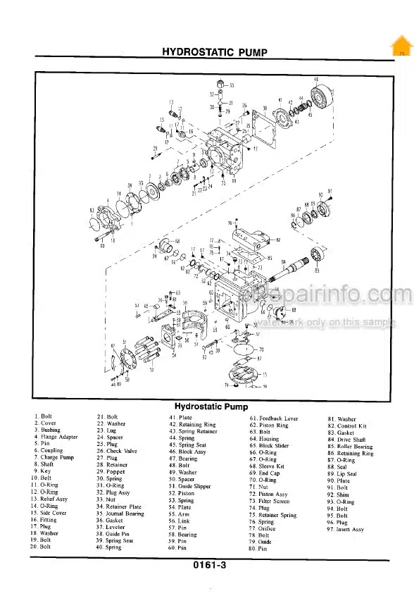
-HYDROSTATIC PUMP
Hydrostatic Pump
Pump Adjustments
Charge Relief Valve Adjustment
Multi-Function Valve Pressure Adjustment
Engaging the Bypass Function
Hydraulic Displacement Control (HOC)
Shaft Seal and Shaft Replacement
Pump Minor Repairs
Multi-Function Valve Cartridges
Charge Relief Valve
Charge Pump
Installing the Charge Pump
Auxiliary Pad Installation
Auxiliary Pad Conversion
Hydraulic Displacement Controls
Displacement Control Components
Displacement Control Filter Screens
Displacement Control Orifice Check Valve
Displacement Control Orifices
Disassembly Procedures for
Variable Displacement Pump
Reconditioning and Replacement of Paris
Assembly Procedures for
Variable Displacement Pump„
0TWO WHEEL/4 WHEEL DRIVE CONTROL VALVES
Control Valve
Theory of Operation
Hydraulic Symbol
Selector Valve
Theory of Operation
Hydraulic Symbol
-FORWARD/REVERSE FOOT PEDAL CONTROL
Forward/Reverse Control Valve
Disassemble and Assemble Foot Controller
Theory of Operation
Solenoid De-energized
Solenoid Energized
-FRONT AXLE MOTOR
Front Axle Ground Drive
Minor Repair—Front Axle Motor
Special Tools
Special Tools
-REAR MOTOR REPAIR
Rear Wheel Motor
Theory of Operation
Repair Instructions
-MINOR REPAIRS
Cover Plate Seals Replacement
Shaft Seal Replacement
Rotary Group Removal
Rotary Group Inspection
Rotary Group Assembly
-MAIN HYDRAULIC SYSTEM
Introduction
The Effect Of Contamination
The Purpose Of Hydraulic Fluid
Component Mechanical Clearances
Definition of Contamination
Component Failure States
Component Contamination Failures
Contaminants In Hydraulic Systems
Hydraulic Oil Storage
Oil Filtration
Hydraulic Components
Aeration and Cavitation
Troubleshooting Tips
All Hydraulic Functions Slow
Hydraulic Function Slow
No Hydraulic Functions
Pump Not Delivering Oil
Insufficient Pressure Buildup In Pump
Pump Making Noise
Slow Steering—Both Directions
High Steering Effort
Directional Control Valve Can’t Get Pressure
Directional Control Valve Delivers Erratic Pressure
No Response When Steering Wheel Is Slowly Turned
Wrong Response To Steering Wheel
Continuous Steering Wheel Rotation
No Response To Steering Wheel
Drive Elements (Coupling, Gears, & Shafts)
Hydraulic Cylinder or Motor
Directional Valves
Flow Control Valves
Accumulators
Pressure Relief Valves
Return Lines
Filters
Coolers
Pressure Gauge
Pressure Line
Diesel Engine
Oil Line Leakage
Suction Line – Characteristics
Oil Tank – Hydraulic Fluid
-PUMP REPAIR
Double Vane Pump
Theory of Operation
Maintenance
Service Tools
General Repair
Pump Disassembly
Disassemble Cartridge Kit
Cartridge Kit
Clean and Inspect
Before Assembly
Cartridge Kit Assembly
Pump Assembly
Troubleshooting
Single Vane Pump
Theory of Operation
Maintenance
Service Tools
General Repair „
Pump Disassembly
Clean and Inspect
Before Assembly
Assembly
-DIRECTIONAL CONTROL VALVE
2 Bank Pilot Operated Directional Control Valve
Suggested Too Is
Relief Settings
Overhaul
Valve Bank Disassembly
Tie Bolts
Section Seals
Transition Check
Pilot Operated Section Disassembly
Control Spool & Seals
Spool Disassembly
Preparation of Parts
Cleaning, Inspection and Repair
Assembly
Spool Assembly—Spring Centered
Section Assembly
Transition Check Assembly
Valve Bank Assembly
Solenoid Operated Section Disassembly
Troubleshooting
Oil Leaks At End Of Spool
Spool Does Not Return To Neutral
No Motion, Slow or Jerky Action of Hydraulic System
No Relief Valve Action (High Pressure)
Load Will Not Hold
Load Drops When Spool Is Moved From Neutral To A Power Position
Joystick
Disassembly
Assembly
-CYLINDER REPAIR
Tools and Supplies
Disassemble
Clean And Inspect
Assemble
Cylinder Leak Test
Test Cylinder
Optional Cushion Theory Of Operation
Adjustment
-RELIEF VALVE
Theory of Operation
Repair
Removal
Disassembly
Clean and inspect
Assembly
Erratic Pressure
Low or No Pressure
Excessive Noise or Chatter
-STEERING SYSTEM
Priority Valve
Theory of Operation
Main Spool Repair
Relief Valve Adjustment
Relief Valve Repair
Repair Instructions
Necessary Tools
Disassembly
Clean And Inspect
Reassembly
Troubleshooting
Slow Steering, Hard Steering or Loss of Power Assist
Wander: Loader Will Not Stay In A Straight Line
Drift: Loader Veers Slowly In One Direction
Slip: A Slow Movement Of Steering Wheel Fails to Cause Any Movement of the Steered Wheels
Hang-Up: Temporarily Hard Steering
Soft Steering
Erratic Steering
Free Wheeling: Steering Wheel Turns Freely With No Feeling of Pressure and No Action on Steered Wheels
Free Wheeling: Steering Wheel Turns with Slight Resistance but Results In Little or No Steered Wheel Action
Excessive Free Play At Steering Wheel
Excessive Free Play At Steered Wheels
Binding Or Poor Centering Of Steering Wheel
Steering Valve Locks-up
Steering Wheel Oscillates Or Turns By Itself
Steered Wheels Turn In Wrong Direction When Operator Activates Steering Wheel
-BRAKE SYSTEM
Theory of Operation
Diagnosing Malfunctions
Removal
Repair
Brake Slave Cylinder
Removal
Clean and Inspect
Assembly and Installation
Brake Master Cylinder
Removal
Disassembly and Repair
Assembly and Installation
Adjusting Master Cylinder
Bleeding the Brake System
Bleeding the Master Cylinder
Bleeding the Slave Cylinders
-OPERATOR’S STATION
Theory Of Operation
Glass And Moldings
Air Intake (Pressurizer) System
Air Conditioning System
Air Conditioning Circuit
Receiver/Dryer Operation
Thermostat Switch Operation
Expansion Valve Operation
Compressor Relief Valve Operation
Heating System
Air Conditioning Specifications
AC Circuit Operational Information
Refrigerant Cautions
R134A Component Oil Charge
R134A Refrigerant Recover, Recycling And Charging System Installation Procedure
Recover R134A System
Evacuate R134A System
Air Conditioning System Test
Charge R134A System
Air Conditioning Operational Checks
Visual Inspection of Components
System Operating Checks
System Performance Checks
Blower/Air Conditioning Circuit
Service Equipment and Tools:
Insufficient Heating
Inadequate Removal of Ice or Fog
Heater Valve Not Shutting Off Coolant Flow
Air Conditioning System Does Not Operate
Air Conditioner Does Not Cool Cab Interior
Air Conditioner Runs Constantly, Too Cold
-TRANSMISSION
Transmission
Differential
Final Drive
Brakes
Transmission Does Not Drive with Engine Running
Transmission Drives in One Direction Only
Transmission Drives Exratically
Noisy Transmission Operation
Lack of Power or Sluggish
Excessive Transmission or Final Drive Noise
Oil Seeping From Outer Axle Seal
Excessive Driveline Vibration
Weak or No Brakes
Brakes Will Not Release
Hissing Noise at Brake Valve
Brakes Apply For A Period of Time and Then Release On Their Own
Brake Will Not Engage Adequately
Brake Is Noisy
Brake Has Excessive Wear
Brake Disc Overheats
Specifications
Necessary Supplies
Drain Oil, Remove Suction Screen
Transmission Removal
Remove and Repair Shifter Forks and Cam
Shifter Fork Installation
Front Cover With Shifter Cam Installation
Remove and Install Lube Pump
Countershaft Removal
Differential Removal
Differential Disassembly
Differential Assembly
Transmission Assembly
Differential Bearing End Play Adjustment
Countershaft Bearing End Play Adjustment
Transmission Installation
-FOUR WHEEL TORQUE HUB REPAIR
Cross Sectional View
Oil Information
Oil Temperature
Oil Change
Oil Fill Level and Volume
Tightening and Torquing Bolts
The Roll Test
The Leak Test
Main Disassembly – Part One
Cover Disassembly
Main Disassembly – Part Two
Hub-Spindle Disassembly – Part One
Hub-Spindle Disassembly- Part Two
First Stage Carrier Disassembly
Second Stage Carrier Disassembly
First Stage Carrier Sub-Assembly
Second Stage Carrier Sub-Assembly
Cover Sub-Assembly
Hub-Spindle Sub-Assembly-Part One
Hub-Spindle Sub Assembly-Part Two
Main Assembly
-ELECTRICAL SYSTEM
Visually Inspect Electrical System
Safety Precautions
Specifications
Theory of Operation
Cleaning Battery Posts
Jumping the Battery
Charging the Batteries
Precautions for Alternators
Inspection
Shorted Circuit
High Resistance or Open Circuits
Grounded Circuits
Ignition Switch Test
Alternator Output Check
Starter Solenoid Check
Starter Motor Check
Start Switch Check {Push Button)
Horn Switch Check
Horn Check
Nothing Works
Some Electrical Components Work
Starter Will Not Crank Engine
Engine Cranks Slowly
Starter Turns, But Engine Will Not Crank
Starter Still Runs After Engine Starts
Low Battery Output
Starter Solenoid Chatters
Noisy Alternator
Gauge Does Not Work (Applies To All Gauges)
Horn Does Not Work
Oil Pressure Sending Unit
Oil Pressure Switch
Engine Coolant Temperature Gauge Sender Engine Coolant Temperature Switch
Hydraulic Oil Temperature Sender
Fuel Sending Unit
Hydraulic Filter Pressure Switch
Air Filter Restriction Switch
What you get
You will receive PDF file with high-quality manual on your email immediately after the payment.
Reviews
There are no reviews yet.