


Factory Technical Manual For John Deere Harvester. Manual Contains Illustrations, Instructions, Diagrams For Step By Step Remove And Install, Assembly And Disassembly, Service, Inspection, Repair, Troubleshooting, Tune-Ups.
Format: PDF
Language: English
Pages: 250
Model
John Deere Cameco Harvester
CH3500
Contents
-GENERAL SPECIFICATIONS
Specifications
John Deere 6081 Engine
Description
Preliminary Service Intervals
Common Wear Parts
-GENERAL CAPACITIES
Harvester Capacities
Tire Inflation Pressure
-TORQUE SPECIFICATIONS
Suggested Torque Values For Grades 5.6,8.8,10.9, 12.9 Zinc Plated Cap Screws
Suggested Torque Values For Grades 5.6,8.8,10.9, 12.9 Zinc Plated Cap Screws
Torque for Grade 2 NC Weld Studs
Suggested Torque Values And Clamp Loads For Grades 2, 5 & 8 Cap Screws
Grade or Property Class Head Marking for SI Bolts
Conversion Factors
-FLUID RECOMMENDATIONS
John Deere Engine Coolant Requirements
John Deere Prediluted Antifreeze/
Summer Coolant
John Deere Cool-Gard
John Deere Antifreeze/Summer Coolant Concentrate
John Deere Antifreeze/Summer Coolant
Hydraulic Fluid
Diesel Fuel
Engine Break-in Oil (John Deere)
Diesel Engine Oil
Gear Oil—Pump Drive, Chopper Box and Basecutter
Gear Oil—Final Drive
Grease
-GENERAL INFORMATION
Straight O-Ring Boss Fittings
Angled O-Ring Boss Fittings
37° Flare Cone Fittings
Hex Flats Recommended Rotation
Four Bolt Flange Fittings
Flange Metric Bolt Torque Chart
Flange SAE Bolt Torque Chart
Conversions
Weight Measure
Length Measure
Metric (Sit) Measurements
Metric to English
English to Metric
Multiplication Factors
Temperature Conversion Chart
Conversion Formulas
Recommended Supplies
Hydraulic Gauge Kit
CH3500 Specialty Tools and Part Numbers
-SERVICE POINTS
Harvester Component Locations
Harvester Service Point Locations
Harvester Grease Point Locations
Grease Point Locations
-ENGINE
Pump Drive
Pump Drive Removal
Disassembly
Clean and Inspect
Assembly
-OPERATOR’S STATION
Other Material
Remove and Install Cab Windshield
Remove and Install Cab Roof
Remove and Install Instructional Seat
Cab Door Latch Striker
-HYDROSTATIC TRANSMISSION
Hydrostatic Pump
Hydrostatic Pump
Manual and Electrical Displacement Control
Suggested Tools And Supplies
General Repair Instructions
Manual and Electrical Displacement
Control Replacement!
Orifice Check Valve Replacement
Charge Pressure Relief Valve Replacement
Shaft Seal Replacement
Multifunction Valve Cartridge Replacement (2 Per Pump)
Charge Pump Disassembly
Charge Pump Reassembly
Variable Displacement Motor (Wheel)
Shaft Seal Disassembly
Inspect
Assembly
About Servicing The Motor
Cartridge Disassembly
Housing Disassembly
Reconditioning and Replacement of Shaft Assembly
Piston Ring Reconditioning and Replacement
Reconditioning and Replacement of Bearing Plate, Valve Segment, and Cylinder Block
4-Way Valve and Feedback Springs
Housing Assembly
Housing Assembly
Fixed Displacement Motor (Track)
Cartridge Assembly
Reconditioning and Replacement of Piston Rings
Cylinder Block Assembly
Cylinder Block Assembly
End Cap to Main Housing Assembly Track Fixed Displacement Motor
Disassembly
-FINAL DRIVE
Safety Information
Installation of the Gearbox to the harvester
Gearbox Lubrication
Oil Filling
Oil Draining and Replacement
Disassembly
Reassembly
Brake Check
-WHEEL AND TRACK
Right Side View
Track Assembly
Track Assembly
Track Alignment
Roller Lubrication
Idler Lubrication
Track Shoe Tightening
Track Shoe Inspection Torque
Sprocket Tightening
Rear Axle Maintenance
Track Adjustment
Front Idlers
Lubrication
Identifying Master Link For Chain Removal
Recoil Spring Repair
Recoil Spring Adjustment
Specifications
Link Rail Wear
Link Rail Measurement
Rebuildability
Link Percentage Worn Chart
Sealed Track Bushings & Pins
Bushing and Pin Wear
Wear Measurement
Wear Limits—Service and Destruction
Track Bushing Allowable Wear Chart
Internal Pitch Wear
Measurement Technique
Detrimental Effects of Excessive Pitch
Allowable Wear
Internal Pitch Percentage Worn Chart
Track Rollers
Track Roller Lubrication
Seal Assembly
Specifications
Carrier Roller
Carrier Roller Lubrication
Carrier Roller Assembly
Specifications
Sprocket Wear Patterns
Sprocket Replacement
Tip Gouged
Rolling Undercarriage
Roller Wear Diagnosis
How To Measure Roller Wear
Specifications
Carrier Roller Percentage Worn
Track Roller Percentage Worn
Rolling Undercarriage
Flange To Boss Measurement
Idler Tread Wear Measurement
Swapping Idlers
Check Idler Flange Wear
Flange Top Wear
Flange Side Wear
Idlers Percentage Worn Chart
Track Shoe Problems
Grouser Wear Measurement
Wear Limits—Service and Destruction
Grouser Wear
Plate Wear and Leading/Trailing Edge Wear
Bolt Hole Wallowing Out
Self-Locking Track Nut
Sprocket Chain Roller Alignment
Wheel Assembly
Wheel Assembly
Remove And Replace Front Wheel Bearings
Suggested Tools
Remove Rear Wheel Assembly
To Remove And Mount Tire Onto Wheel Assembly
Install Wheel Assembly
Tire Pressure Specifications
-MAIN HYDRAULIC SYSTEM
Multiple Gear Pump
World Multiple Gear Pump
World Multiple Gear Pump (Piggyback)
Multiple Gear Pump Repair
Suggested Tools
Repair Precautions
Bushing Removal Tool
Seal Removal Tool
Bushing Installation Tool
Special Steel Sleeve
Seal Installation Tool
Disassembly
Clean and Inspect
Assembly
Start Up Procedure
Recommended Test Procedure
External Relief Settings
Overhaul
Valve Bank Disassembly
Front and Rear Feed Roller Valves
Assembly Procedure
Track Fixed Displacement Motor
Seal Replacement
Disassembly
Clean and Inspect
Assembly
-STEERING SYSTEM
Relief Valve Adjustment
Relief Valve Repair
Priority Valve
Disassembly/Reassembly
Troubleshooting
Steering Linkage
Remove and Install Steering Cylinder
Repair Steering Cylinder
Check Front Axle Toe-In
Adjust Front Axle Toe-In
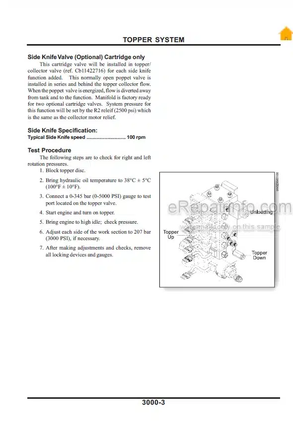
-TOPPER SYSTEM
Collector, Crop Divider, Feed Roller, and
Elevator Motor
Suggested Tools
Collector Motor
Disassembly
Clean and Inspect
Assembly
Topper
Topper Repair
Collector Drum and Motor Removal
Topper Assembly Removal
Clean and Inspect
Drum and Topper Assembly
Shredder Topper
Topper Repair
Collector Drum and Motor Removal
Topper Assembly Removal
Clean and Inspect
Drum and Topper Assembly
Scroll Cylinder
Suggested Tools
Disassembly
Clean And Inspect
Assembly
Topper Lift
Disassemble and Assemble Topper
Lift Cylinder
Gear Motor
Gear Motor Repair
Suggested Tools
Repair Precautions
Bushing Removal Tool
Seal Removal Tool
Bushing Installation Tool
Disassembly
Clean And Inspect
Assembly
Start Up Procedure
Recommended Test Procedure
-CROP DIVIDER SYSTEM
Crop Divider
Crop Divider Removal
Disassembly
Clean and Inspect
Assembly
Crop Divider Shoe Assembly
Crop Divider Shoe Removal
-FEEDROLLER SYSTEM
Knockdown Roller
Buttlifter Roller (B1)
Bottom Feed Roller (B2, B3, B4, B5)
Top Floating Feed Roller (T1,T2,T3,T4,T5)
-BASECUTTER SYSTEM
Basecutter Gearbox
Leg Shaft Removal
Basecutter High Drive Assembly
Basecutter Lift Cylinder (Wheel)
Wheel Basecutter Lift Cylinder Disassembly
Basecutter Lift Cylinder (Track)
Suggested Tools
Track Basecutter Lift Cylinder Disassembly
-CHOPPER SYSTEM
Remove
Chopper Gearbox Pre-Assembly and Installation
Top and Bottom Drum Installation
Final Assembly of Chopper Box
Differential Chopper Blade and Kicker Installation
Differential Chopper Timing and Adjustments
Chopper System
Differential Chopper Timing
Slip Clutch
Disassembly
Assembly (Flywheel, Slip Clutch Assembly and Adjustment)
Field Setting of Slip Clutch
Clean and Close Box
Assembly Chopper Motors
Assembly Chopper Deflector Shields and Adjustments
Install and Adjust Sill Plate
Chopper Motor Repair and Overhaul
Shaft Seal and Cover
Drive End Cover and Seal
Distributor End Cover and Seal
Distributor Housing and Seal Dismantling
Assembly
Distributor Piston Rings
Crankshaft and Cylinder Block Assembly
Inspection and Repair
Assembly
Procedure for Preloading Taper Roller Bearing on Motor
Bearings
Pistons and Piston Seals
Piston Pads
Testing
Hydraulic Test
-CLEANING SYSTEM
Fan Assy
Installing The Hub To Motor Shaft
Installing Fan Blades, Doubler Plates, and Backing Plate
Safety Startup
Variable Primary Extractor Pump
Manual Displacement Control
Suggested Tools
Multi-Function Valve Adjustment
Stroke Limiter Adjustment!
Charge Relief Adjustment
Minor Repair
General Repair
Manual Displacement Control Replacement
Orifice Check Valve Replacement
Charge Pressure Relief Valve Replacement
Shaft Seal Replacement
Multi-Function Valve Cartridge Replacement (2 per pump)
Charge Pump Disassembly
Reassembly
Primary Extractor Motor
Tools Required
Disassembly Shaft Seal
Disassembly End Cover with Integral Shuttle and Low Pressure Relief Valve
Disassembly of End Cover
Disassembly of Rotating Group
Reassembly
Reassembly of Shaft Seal
Reassembly of End Cover
Shaft Bearing Cone Driver (End Cover end)
Low Clearance Bearing Puller
-ELEVATOR SYSTEM
Standard Capacity Elevator System
Elevator Group
Chain Adjustment
Changing Chain and Sprockets
Headshaft Repair
What you get
You will receive PDF file with high-quality manual on your email immediately after the payment.


Reviews
There are no reviews yet.