


Factory Service Training And Workshop Handbook For Komatsu Wheel Loader. Manual Contains Illustrations, Instructions, Diagrams For Step By Step Remove And Install, Assembly And Disassembly, Service, Inspection, Repair, Troubleshooting, Tune-Ups.
Format: PDF
Language: English
Pages: 226
Number: 2974801M1
Wiring Diagrams: Yes
Hydraulic Diagrams: Yes
Model
Komatsu Wheel Loader
60E
Contents
-GENERAL
Safety Precautions
Safety Equipment
Technical Data
Operation
Maintenance
Test Certificate
ENGINE
-TORQUE CONVERTER AND POWERSHIFT TRANSMISSIONS
Arrangement Of The Components In The Machine
Engine – Converter And Transmission Hydraulic Circuit Diagram
Electrohydraulic Gearshift Control Unit Circuit Diagram
External View Of The Torque Converter Transmission
Cross Section Of The Complete Torque Converter Transmission
Torque Converter And Powershift Pump
External View Of The Powershift Transmission
Cross Section Of The Powershift Transmission
Pressure Regulating Valve
Electrohydraulic Gearshift Control Unit
Gear Selection Levers On Steering Column
Gear Selection Mechanism And Switches
Electrohydraulic Gearshift Electrical Wiring Diagram
-LOADER AND STEERING HYDRAULIC SYSTEM
Block Diagram Of The Loader And Steering Hydraulic System
Hydraulic Circuit Diagram For Systems With A 2-Spool Directional Control Valve
Loader-And-Steering Pump And Loader Pump
Loader Hydraulics – Unloading Valve Block
Loader Hydraulics – 2-Spool Directional Control Valve
Arrangement Of Valves In The 2-Spool Directional Control Valve
Loader Hydraulics – Servo (Remote Power Control) Pressure Holding Valve
Loader Hydraulics – 2-Spool Servo (Remote Power Control) Control Valve
Hydraulic Cylinders
Bearing And Pivoting Points On The Loader Frame
Bucket Linkage Stops
-STEERING SYSTEM
Steering System Hydraulic Circuit Diagram
Steering Valve Block
Steering Valve Block Faults And Remedies
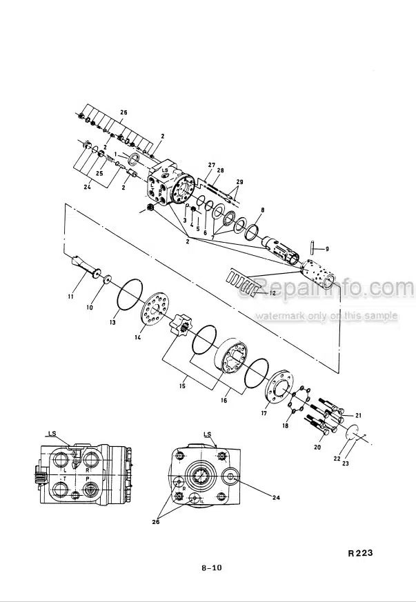
Exploded View Of The Hydrostatic Steering Unit
Emergency Steering Pump: Exploded View; Description; Operation
Steering Cylinder With Cushioning Device: Cross Section; Dismantling And Re-Assembling; Operation Of The Cushioning Device
-AXLES
Tires And Inflation Pressures
Rear Axle Oscillating Angle
Multi-Disc Self-Locking Differential
Front And Rear Axle Differentials
Front And Rear Axle Final Reduction (Hub) Assemblies
Axle Disconnect
-BRAKE SYSTEM
Dual-Circuit, Power Hydraulic Brake System Circuit Diagram
Unloading Valve
Dual-Circuit Brake Pedal Valve
-FRAMES
Cross Sections Of The Rear Axle Cradle And Centre Pivot Bearings
Driver’s Cab Mountings
-ELECTRICAL SYSTEM
Electronic, Digital Speed Indicator (Speedometer)
Fuses And Relays
Electrical Wiring Diagrams: Front Frame; Rear Frame; Electrohydraulic Gearshift; ALS System
What you get
You will receive PDF file with high-quality manual on your email immediately after the payment.


Reviews
There are no reviews yet