


Factory Shop Manual For Komatsu Pipelayer. Manual Contains Illustrations, Instructions, Diagrams For Step By Step Remove And Install, Assembly And Disassembly, Service, Inspection, Repair, Troubleshooting, Tune-Ups.
Format: PDF
Language: English
Pages: 550
Number: SEBM029900 (july 2004)
Bookmarks: Yes
Searchable: Yes
Wiring Diagrams: Yes
Hydraulic Diagrams: Yes
Model
Komatsu Pipelayer
D355C-3
SN 14263 And Up
Contents
FOREWORD
-GENERAL
General Assembly Drawing
Specifications
Weight Table
Table Of Fuel, Coolant And Lubricants
-STRUCTURE AND FUNCTION
Radiator Fan
Radiator Shutter
PTO (Power Take-Off)
Oil Cooler
Powertrain Diagram
Torqflow Hydraulic Circuit
Power Train Hydraulic Circuit Diagram
Torque Converter
Transmission Control
Torqflow Transmission
Transmission Control Valve
Transmission Lubrication Valve
Steering And Brake Control
Bevel Gear Shaft And Steering Clutches
Steering And Brake Hydraulic Piping
Steering And Brake Hydraulic Circuit Diagram
Steering Brakes
Steering Control Valve
Final Drive
Track Group
Recoil Spring
Suspension
Winch Control
Hydraulic Circuit Diagram For Winch
Winch
Detailed Working Circuit Diagram For Clutch And Brake Of Winch
Powertrain Of Winch
High-Low Valve
PPC Valve
Flow Divider Valve
Counterweight Hydraulic Tank
Counterweight Piping
Counterweight Control
Counterweight Hydraulic Circuit Diagram
Counterweight
Counterweight Control Valve
Boom
Safety Device
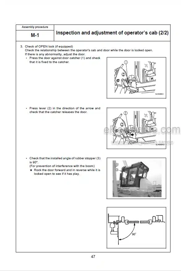
Cab
Heater
Actual Electrical Wiring Diagram
-TESTING AND ADJUSTING
Standard Value Table For Engine Related Parts
Standard Value Table For Chassis
Testing And Adjusting
Troubleshooting
-DISASSEMBLY AND ASSEMBLY
Precautions When Carrying Out Operation
Special Tool List
Removal And Installation Starting Motor Assembly
Removal And Installation Alternator Assembly
Removal And Installation Of Engine Oil Cooler Core Assembly
Removal And Installation Of Fuel Injection Pump Assembly
Removal And Installation Of Water Pump Assembly
Removal And Installation Of Turbocharger Assembly
Removal And Installation Of Nozzle Holder Assembly
Removal And Installation Of Cylinder Head Assembly
Removal And Installation Of Thermostat Assembly
Removal And Installation Of Radiator Assembly
Removal And Installation Of Fuel Tank Assembly
Removal And Installation Of Torque Converter And Winch Cooler Assembly
Removal And Installation Of Engine Assembly
Removal And Installation Of Transmission Pump Assembly
Removal And Installation Of Floor Frame Assembly
Disassembly And Assembly Of Torque Converter Assembly
Removal And Installation Of Torque Converter Assembly
Removal And Installation Of Torque Converter Relief Valve Assembly
Removal And Installation Of Torque Converter Regulating Valve Assembly
Removal And Installation Of Transmission Control Valve Assembly
Removal And Installation Of Torqflow Transmission Assembly
Disassembly And Assembly Of Torqflow Transmission Assembly
Removal And Installation Of Steering Control Valve Assembly
Disassembly And Assembly Of Steering Control Valve Assembly
Removal And Installation Of Brake Safety Valve Assembly
Disassembly And Assembly Of Brake Safety Valve Assembly
Removal And Installation Of Transmission Lubrication Valve Assembly
Removal And Installation Of Steering Pump Assembly
Removal And Installation Of Steering Clutch Assembly
Disassembly And Assembly Of Steering Clutch Assembly
Removal And Installation Of Fuel Tank Assembly
Removal And Installation Of Bevel Gear And Bevel Gear Shaft
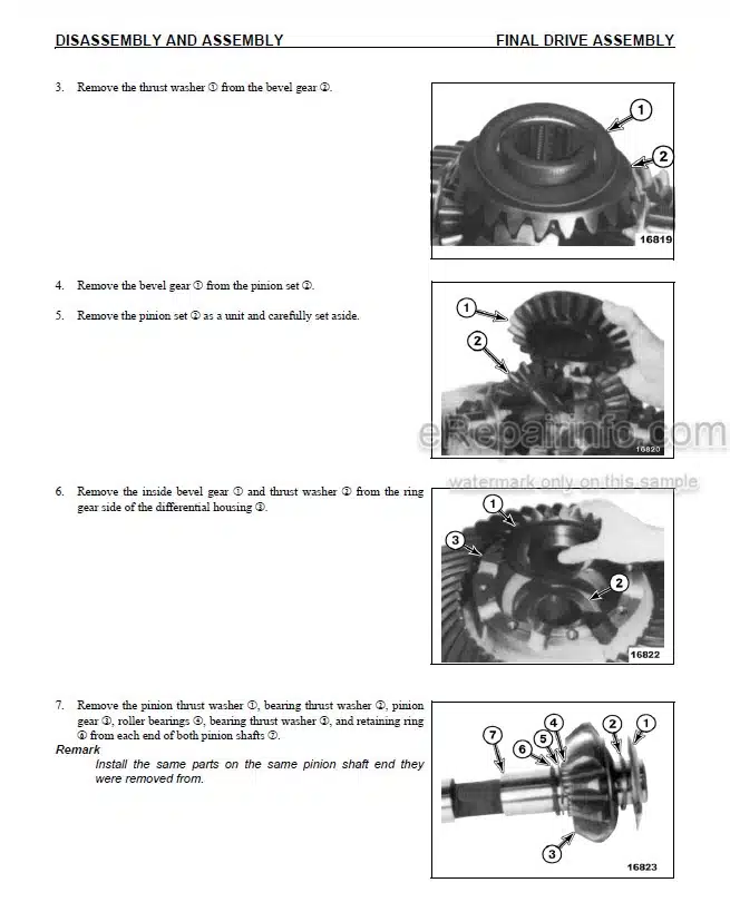
Disassembly And Assembly Of Final Drive Assembly
Removal And Installation Of Track Assembly
Removal And Installation Of Carrier Roller Assembly
Removal And Installation Of Track Roller Assembly
Removal And Installation Of Idler Assembly
Disassembly And Assembly Of Recoil Spring Assembly
Removal And Installation Of Track Frame Assembly
Removal And Installation Of Winch Control Valve Assembly
Disassembly And Assembly Of Winch Control Valve Assembly
Removal And Installation Of High/Low Speed Selector Valve Assembly
Disassembly And Assembly Of High/Low Speed Selector Valve Assembly
Removal And Installation Of Towing Winch Pump Assembly
Removal And Installation Of Counterweight Pump Assembly
Removal And Installation Of Counterweight Cylinder Assembly
Removal And Installation Of Counterweight Control Valve Assembly
Disassembly And Assembly Of Counterweight Control Valve Assembly
Removal And Installation Of Gate Frame Assembly
Removal And Installation Of Counterweight/Frame
Removal And Installation Of Boom/Frame
Removal And Installation Of Towing Winch Assembly
Disassembly And Assembly Of Towing Winch Assembly
Removal And Installation Of Heater Assembly
-MAINTENANCE STANDARD
Engine Mount
PTO
Torqflow Transmission
Transmission Pump
Bevel Gear Shaft And Steering System
Steering Pump
Final Drive
Track Frame
Recoil Spring
Track
Idler
Track Roller
Carrier Roller
Suspension
Winch Pump
Counterweight Pump
HI-LO Valve
PPC Valve
Flow Divider Valve
Winch
Lower Clutch
Raise Clutch
Winch Brake
Control Valve (For Counterweight)
Counterweight Cylinder
Slow Return Valve
Counterweight
Boom
-OTHERS
Electric Circuit Diagram (STD)
Electric Circuit Diagram (-50°C Spec.)
Cab Electric Circuit Diagram
What you get
You will receive PDF file with high-quality manual on your email immediately after the payment.


Reviews
There are no reviews yet.