


Factory System Manual For Kramer Telehandler. This Manual Describes The Function, System And Components Of The Machine.
Format: PDF
Language: English
Pages: 1252
Issued: february 2019
Bookmarks: Yes
Searchable: Yes
Wiring Diagrams: Yes
Hydraulic Diagrams: Yes
Model
Kramer Telehandler
4209
4407
5007
5507
5509
KT429
KT447
KT507
KT557
KT559
Contents
-INTRODUCTION
Tightening Torques
Symbol And Abbreviations
Safety Instructions
Notes On System Manual
-ENGINE
Overview TCD 3.6
Lubricant Oil System TCD 3.6
Fuel System TCD 3.6
Cooling System TCD 3.6
Turbocharging TCD 3.6
Exhaust Gas Recirculation EGR TCD 3.6
Electric Components TCD 3.6
Overview Of Components TCD 4.1
Lubricant Oil System TCD 4.1
Fuel System TCD 4.1
Cooling Circuit TCD 4.1
Turbocharging TCD4.1
Exhaust Gas Recirculation EGR TCD 4.1
Electric Components TCD 4.1
Exhaust Aftertreatment TCD 3.6
Exhaust System Only For EDG
Exhaust Aftertreatment TCD 4.1
Exhaust System Only For EDG
Starting The Engine
Diesel Engine Monitoring
Diesel Engine Monitoring Components
Component Description Of The Diesel Engine Monitoring
Exhaust After-Treatment (EAT)
Heating Circuit Of SCR System
-COOLING
Cooling Control
Components Of The Component Control
Functional Description Of The Cooling
Cooling Component Description
Cooling Test Report
-POWER TRAIN
Drive Control
Function Description Of Travelling Drive
Drive System With H1P And ICVD
Adjustment Work For Drive System
Error Descriptions
Drive System With H1P And P370
Adjustment Work For Drive System
Error Descriptions
-BRAKES
Brake Control
Trailer Compressed Air Brake Control
Functional Characteristics Of The Brake System
Description Of Braking System Elements
Element Description For The Compressed Air System
Braking System Test Logs
Trailer Brake Test Log
Compressed Air Brake System Test Log
-STEERING
Steering System Actuation
Function Description: Steering System
Test Report Steering
-HYDRAULICS
Lifting Cylinder / Load Stabilizer Actuation
Control Of The Overload Control
Tilt Ram Control
Bucket Repositioning Control
3Rd Control Circuit (Control)
Control Of The 3Rd Control Circuit With Changeover Valve
Tipper Control
Control Of The Tipper/Auto-Hitch
Adjust The Sensor Plate Sensor S137
Rear Additional Control Circuit Actuation
Actuation Of Additional Control Circuit, Large, Front
Control Of The Leveling Model 416-26, 416-29
Control Of The Leveling And Tipper Model 416-26, 416-29
Control Of The Leveling, Tipper, Hitch Model 416-26, 416-29
Control Of The Lock Cylinder Model 416-26, 416-29
Functional Description Of Hydraulic Components
Work Hydraulics Test Logs
Checking Secondary Valves
Hydraulic Diagrams
-ELECTRICAL SYSTEM
Can Signals Component Overview
Inputs/Outputs For Diesel Engine Electronics N005
Controller N015 For Cab Inputs/Outputs
Controller N004 For Frame Inputs/Outputs
Inputs/Outputs For Drive Electronics N001
Inputs/Outputs For Additional Controller N016
Telematic Module N018 Inputs/Outputs
Drive Interlock N021 Inputs/Outputs
Oil Volume Setting N023 Inputs/Outputs
Inputs/Outputs For Steering Electronics D001
Display P014 Inputs/Outputs
Descriptions Of Electric Components
Fuses, Relay
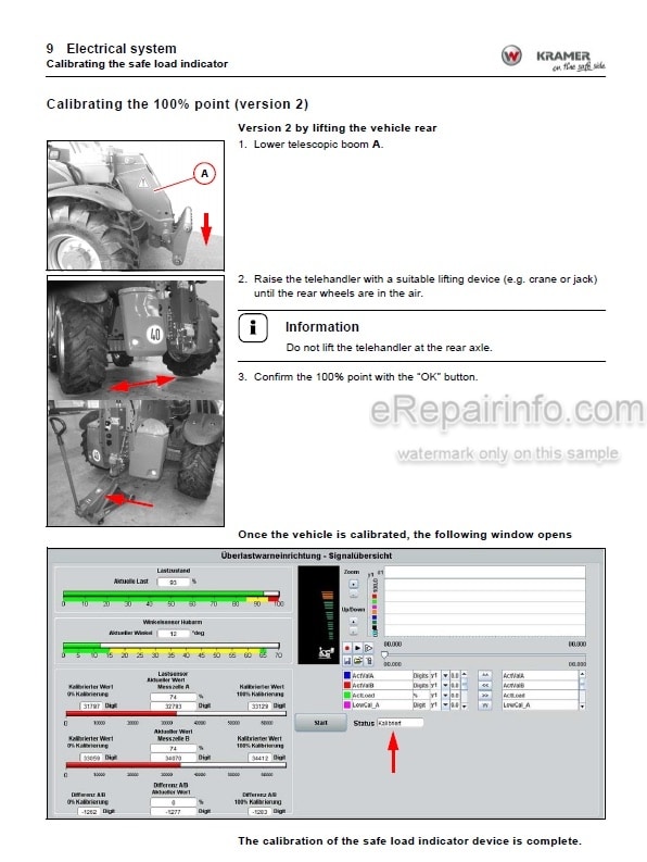
Safe Load Indicator In The Display P014
Calibrating The Safe Load Indicator
Basic Setting Of The Travel Sensor B028
Camera (Front)
Rear Camera
Diagrams
-HEATING/AIR CONDITIONING
Control Of Heating, Air Conditioning
Safety Instructions For The Air-Conditioning System
-INSTALLATION POSITION
Hydraulics
Installation Position Of Electrics
Installation Position Of The Compressed Air System
-SWITCHES
Switch Assignment With Symbols And Installation Location
-CONNECTORS
Plug Frame
Motor Wiring Harness Connectors
Cab Plug
-ERROR CODES
Error Code List
-CENTRAL LUBRICATION SYSTEM
Central Lubrication System
Central Lubrication System: Lubrication Plan
Central Lubrication System: Lubrication Points
What you get
You will receive PDF file with high-quality manual on your email immediately after the payment.


Reviews
There are no reviews yet.