Factory Service Manual For Link-Belt Excavator. Manual Contains Illustrations, Instructions, Diagrams For Step By Step Remove And Install, Assembly And Disassembly, Service, Inspection, Repair, Troubleshooting, Tune-Ups.
Format: PDF
Language: English
Pages: 717
Issued: february 2006
Searchable: Yes
Wiring Diagrams: Yes
Hydraulic Diagrams: Yes
Model
Link-Belt Excavator
700LX
Contents
-GENERAL INFORMATION
Safety, General Information And Standard Torque Data
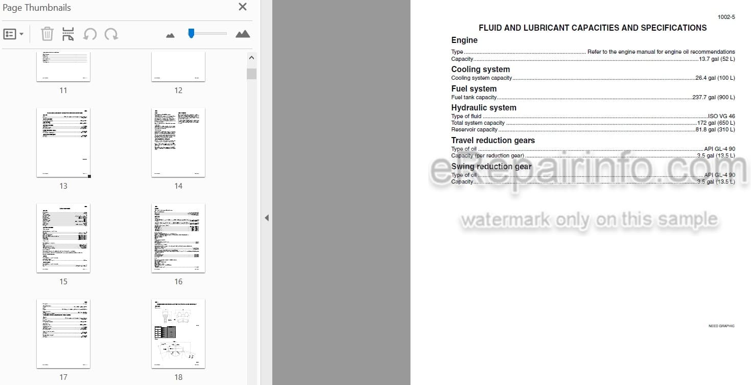
Specifications And Special Torque Settings
-ENGINE
Removing And Installing The Engine
Radiator And Oil-Cooler
-FUEL SYSTEM
Removing And Installing The Fuel Tank
-ELECTRICAL SYSTEM
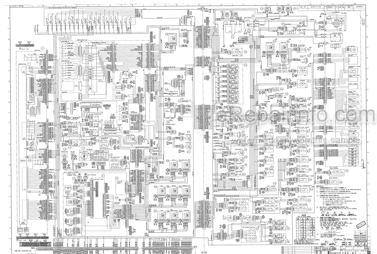
Electrical And Electronic Circuit And Troubleshooting
Inspection And Maintenance Of Batteries And Connecting A Booster Battery
Computer And Engine Controller
-UNDERCARRIAGE
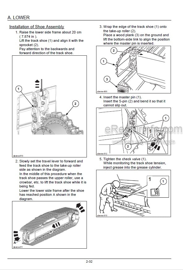
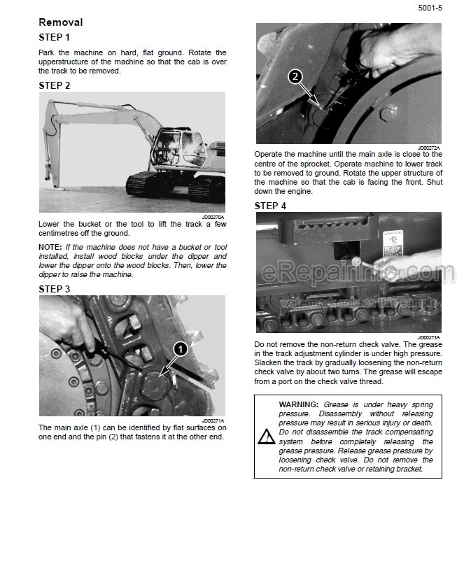
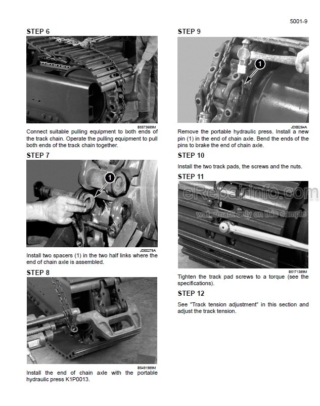
Removal And Installation Of The Tracks Set
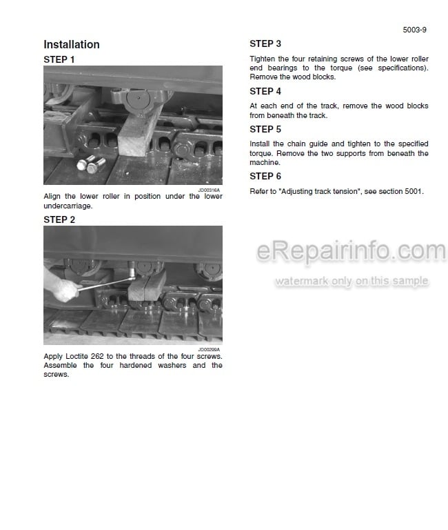
Upper And Lower Rollers
Sprocket
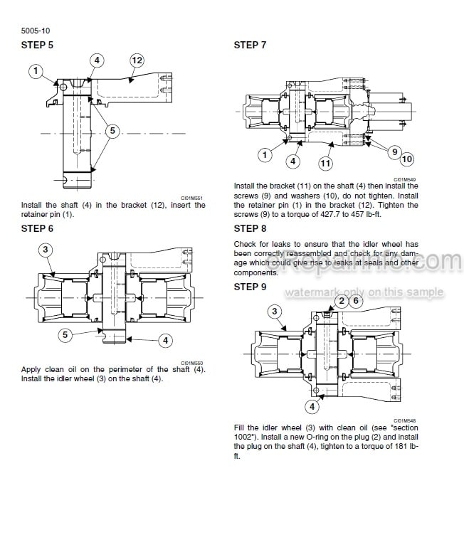
Idler Wheel And Tension Shock Absorber
-DRIVE TRAIN
Removing And Installing The Travel Motor/Reduction Gear Assembly
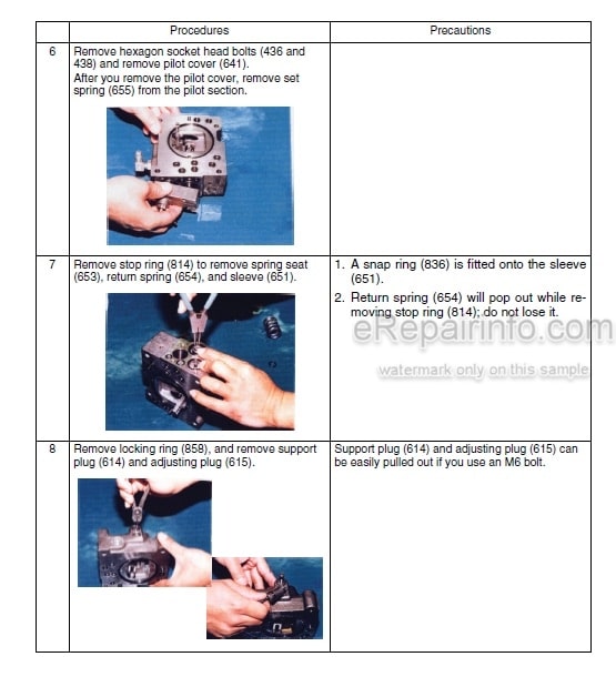
Disassembly And Reassembly Of The Drive Motor And The Travel Reduction Gear
Removing And Installing The Swing Reduction Gears
Swing Reduction Gear
-UPPERSTRUCTURE HYDRAULICS
Pressure Release And Decontamination Of The Hydraulic System, Use Of The Vacuum Pump And Bleeding Of The Components
Troubleshooting Checks And Hydraulic Pressure Settings
Removing And Installing The Hydraulic Reservoir
Removing And Installing The Main Hydraulic Pump And The Pilot Pump
Removing And Installing The Main Hydraulic Control Valve
Removal And Installation Of The Attachment Cylinders
Removing And Installing The Hydraulic Swivel
Removing And Installing The Pilot Function Blocks
Installation And Removal Of The Swing Motors
Disassembly And Assembly Of The Free Swing Valve
Main Hydraulic Pump
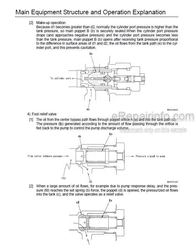
Disassembly And Reassembly Of The Control Valve
Disassembly And Assembly Of The Attachment Cylinders
Disassembly And Assembly Of The Control Levers
Disassembly And Assembly Of The Control Pedals
Disassembly And Assembly Of The Eight Solenoid Valve Bank
Disassembly And Assembly Of The Cushion Control Valve
Safety Valves
Disassembly And Assembly Of The Hydraulic Swivel
Disassembly And Reassembly Of The Hydraulic Swing Motor
Hydraulic Functions
-UPPERSTRUCTURE
Upperstructure, Turntable And Counterweight
Boom, Arm And Bucket
Seat And Safety Belt
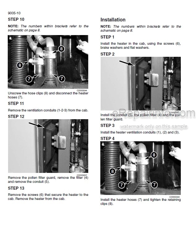
Cab And Cab Equipment
Removal And Installation Attachment, Counterweight And Side Frame
700 LX TIER III EX ELECTRICAL SCHEMATIC (PRINT A)
700 LX TIER III EX ELECTRICAL SCHEMATIC (PRINT B)
700 LX TIER III EX HYDRAULIC SCHEMATIC
What you get
You will receive PDF file with high-quality manual on your email immediately after the payment.
Reviews
There are no reviews yet.