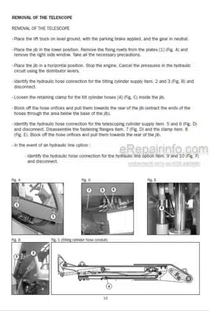
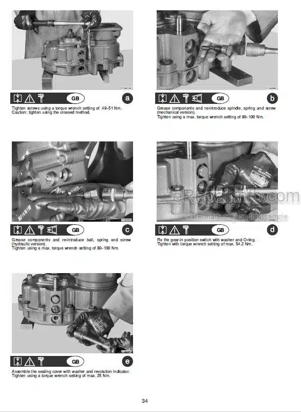
Factory Repair Manual For Manitou Telehandler. Manual Contains Illustrations, Instructions, Diagrams For Step By Step Remove And Install, Assembly And Disassembly, Service, Inspection, Repair, Troubleshooting, Tune-Ups.
Format: PDF
Language: English
Pages: 331
Number: 53111319EN
Searchable
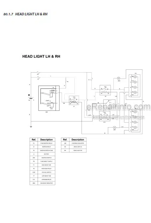
Wiring Diagrams
Hydraulic Diagrams
Model
Manitou Telehandler With Perkins Engine
MXT 1740
Contents
-GENERAL CHARACTERISTICS
General Instructions And Safety Notice
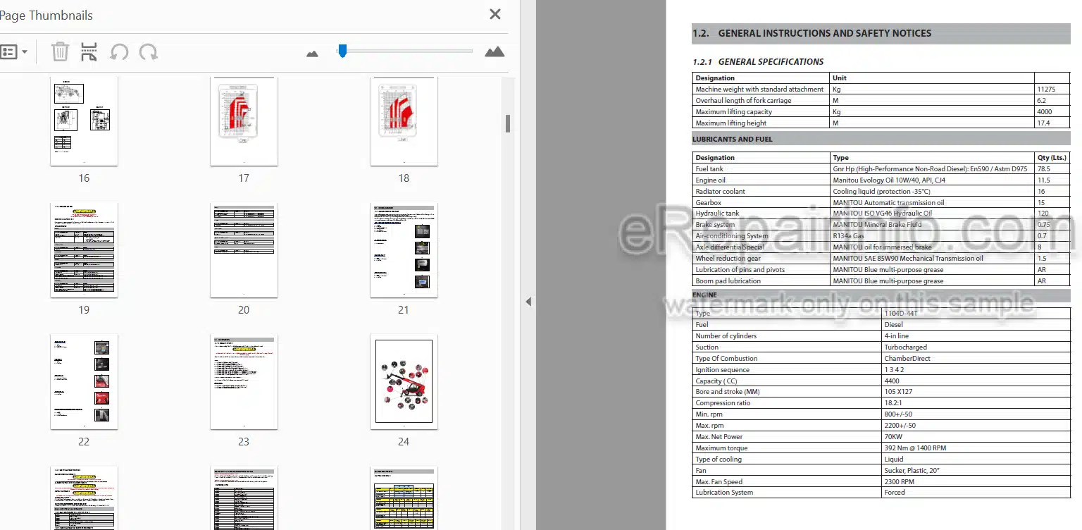
General Characteristics And Specifications
General Location
Maintenance
General Control And Adjustment
-ENGINE
Engine Components Location
Tightening Torques
Air Intake System – Removal And Installation
Starter Motor – Removal And Installation
Attachment Belt – Removal And Installation
Exhaust System – Removal And Installation
Fuel Circuit – Removal And Installation
Cooling System – Removal And Installation
Engine-Removal
Engine-Installation
-TRANSMISSION
Transmission Assembly
Transmission Removal And Installation
Transmission Tightening Torques
Gear Box And Converter
Gear Box (Details)
Gear Box (Details)
Gear Box (Mechanism Details Gears)
Gear Box (Mechanism Details Gears)
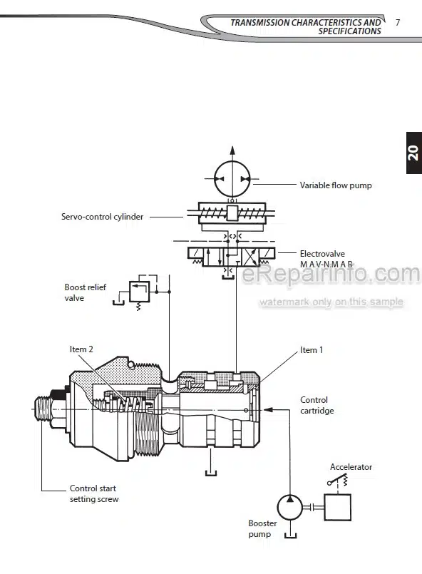
Gear Box (Electrical Control Valve Details)
Transmission Hydraulic Circuit
Description Of The Transmission Shaft Hydraulic Circuit
Transmission Hydraulic Principle Circuit
Transmission Maintenance
Pressure Checking
Pressure Reading On Gearbox
Special Tools
Shaft And Gear End Float Tolerances
Disassembly & Reassembly-General Information
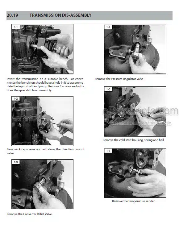
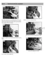
Disassembly & Reassembly-Transmission Dis-Assembly
Disassembly & Reassembly-Input Shaft Dis-Assembly And Re-Assembly
Disassembly And Re Assembly Of The Reverse Idler Shaft
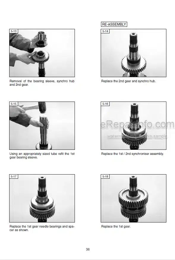
Output Shaft Dis Assembly And Re Assembly
Permanent 4 Wheel Shaft Dis Assembly And Reassembly
Dis Assembly And Re Assembly Of The Oil Pump
Dis Assembly And Re Assembly Of The Valve
Gear Lever Housing Dis Assembly And Re Assembly
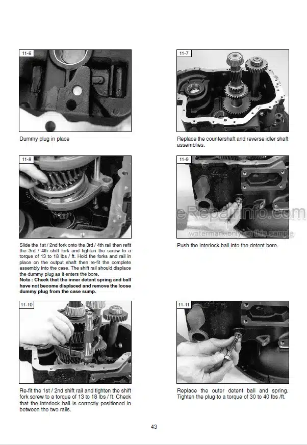
Transmission Reassembly
Test Procedure-Compact Plus Test Procedure
-AXLE
Specifications
Safety Precautions
Checking Wear And Replacing The Braking Discs
Complete Steering Case
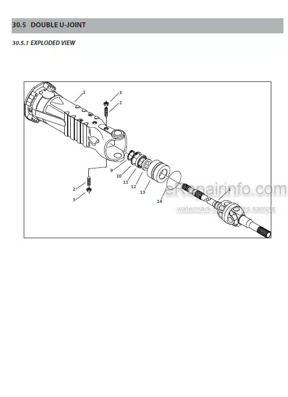
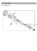
Double U-Joint
Planetary Reduction Gear
Steering Cylinder
Differential Unit
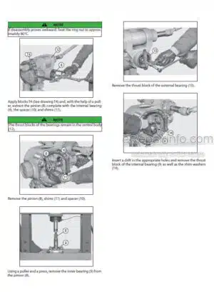
Bevel Pinion
Manual Emergency Release
Mechanical Parking Brake
Normal Differential Unit
Limited Slip Differential Unit (25% And 45%)
Hydraulic Differential Lock
-BRAKE
Brakes – Service Brake And Parking Brake
Service Brake – Removal And Installation
Brake Bleeding Procedure
Brake Adjustment Procedure
Parking Brake – Removal And Installation
-BOOM
Boom Characteristics And Specifications
Boom Schematic Diagrams
Boom Components Location
Boom Control And Adjustment
Specific Boom Tooling
-HYDRAULICS
Cylinder Assembly And Disassembly
Cylinders Drawings
Hydraulic Schematic Diagram
-ELECTRICITY
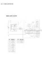
Electrical Schematic
-DRIVER’S CAB
Driver’s Cab – Removal And Installation
Driver S Seat Removal And Installation
-FRAME-BODY
Tank Cover Removal And Installation
-OPTIONS-ATTACHMENTS
Air Conditioning Option – Characteristics And Specifications
Air Conditioning Location
Air Conditioning Controls & Adjustments
Air Conditioning Belts – Removal
Air Conditioning Trouble Shooting
What you get
You will receive PDF file with high-quality manual on your email immediately after the payment.

Reviews
There are no reviews yet.