


Factory Service And Maintenance Manual For Manitowoc Crane. Manual Contains Important Information And Instructions For Maintenance Description Of The Functions And Capabilities Of The System. Illustrations, Instructions, Diagrams For Step By Step Remove And Install, Assembly And Disassembly, Service, Inspection, Repair, Troubleshooting, Tune-Ups.
Format: PDF
Language: English
Pages: 692
Number: CTRL218-02 (october 2013)
Bookmarks: Yes
Searchable: Yes
Wiring Diagrams: Yes
Hydraulic Diagrams: Yes
Model
Manitowoc Crane
10000A-1
SN 1100Ref
Contents
-REFERENCE MATERIALS
10000A-1 Specification
10000A-1 Dimension, Weight Of Each Component
10000A-1 Swing And Propel Stability
10000A-1 Propel Allowable Slope Angle
Engine Main Specification
-TEST PROCEDURES
Maintenance Standard
Performance Standard And Test Procedure
-GENERAL
Tightening Torque Of Cap Screws And Nuts
Standard Parts
Conversion Table
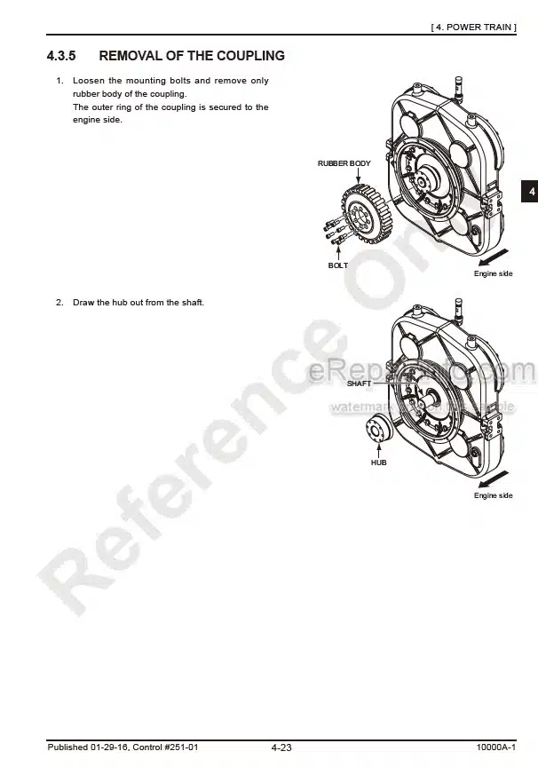
-POWER TRAIN
Introduction
Engine
Pump Drive Assembly
-HYDRAULIC SYSTEM
Location Of Main Hydraulic Components
Hydraulic Circuits And Components
Hydraulic System
Valve
-HOIST SYSTEM
Apparatus And Location Of Components
Adjustment Of Drum Lock
Winch
Brake Pedal
Bleeding Air From Brake Circuit
Construction And Function
-BOOM HOIST SYSTEM
Apparatus And Location Of Components
Boom Hoist Winch Installation
Boom Drum Lock
Reduction Unit
Construction And Function
-SWING SYSTEM
Apparatus And Location Of Components
Construction And Function
Swing Reduction Unit
Swing Bearing
Swing Lock
-PROPEL SYSTEM
Apparatus And Location Of Components
Propel Reduction Unit
Adjustment
Construction And Function
-ELECTRICAL SYSTEM
Electrical
Load Safety Device
Main Controller
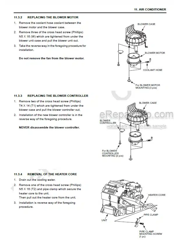
-AIR CONDITIONER
Air Conditioner
Parts Illustration
Disassembly And Assembly Of The Unit
Fault Detection From The Control Panel Indication
Basic System Of HVAC
Recharging Of The Coolant
Electric Wiring Diagram
-TROUBLESHOOTING
Troubleshooting
What you get
You will receive PDF file with high-quality manual on your email immediately after the payment.


Reviews
There are no reviews yet.