


Factory Service And Maintenance Manual For Manitowoc Crane. Manual Contains Important Information And Instructions For Maintenance Description Of The Functions And Capabilities Of The System. Illustrations, Instructions, Diagrams For Step By Step Remove And Install, Assembly And Disassembly, Service, Inspection, Repair, Troubleshooting, Tune-Ups.
Format: PDF
Language: English
Pages: 352
Number: CTRL077-03 (july 2015)
Bookmarks: Yes
Searchable: Yes
Model
Manitowoc Crane
31000
SN 31001Ref
Contents
-INTRODUCTION
Continuous Innovation
Safety Messages
Safe Maintenance Practices
Environmental Protection
Identification and Location of Major Components
General Abbreviations
General Crane Operation
-HYDRAULIC SYSTEM
Hydraulic Schematics
Hydraulic System – General
Checking and Replacing Hydraulic Hoses
Hydraulic System – Maintenance
Hydraulic Solenoid Valve Identification
Inspecting System
Hydraulic Component Identification
Hydraulic System Specifications
Accessory System Checks
Hydraulic System Test, Calibration, and Adjustment Procedures
Section 2 Inserts
-ELECTRICAL SYSTEM
Electrical Schematics
Checking and Replacing Electrical Components
Circuit Breaker, Junction boxes & Node Locations
Rotating Bed Angle Sensor
Fire Suppression Control Relays
Electrical Control System Overview
Test Voltages
Node Diagnostics (CAN Bus diagnostic Screen)
Checking Electrical Inputs/Outputs
Dielectric Grease
Connector Pin Identification
Section 3 Inserts
-BOOM
Boom Hoist System Operation
Automatic Boom Stop
Physical Boom Stop
Physical Luffing Jib Stop
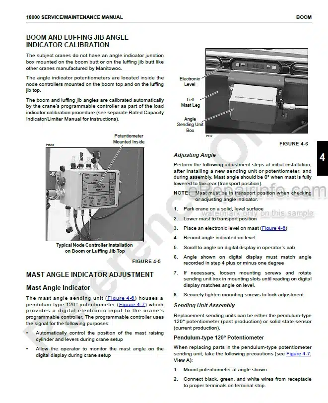
Boom and Luffing Jib Angle Sensor Calibration
Actuator Mast Pocket Limit Switch
Removing Upper Boom Point
Boom Components
Upper Boom Point Components
Aircraft Warning Light
Strap Inspection And Maintenance
Boom, Jib, Backhitch, And Mast Inspection/Repair
-HOISTS
Main Hoist
Main Hoist (Drum 1) System Diagnostics Overview
Main Hoist (Drum 2) System Diagnostics Overview
Main Hoist (Drum 3) System Diagnostics Overview
Main Hoist (Drum 1) Electrical Circuit
Main Hoist (Drum 2) Electrical Circuit
Main Hoist (Drum 3) Electrical Circuit
Luffing Drum 5 (Optional)
Luffing Hoist (Drum 5) Diagnostics Overview
Luffing Hoist (Drum 5) Electrical Circuit
Load Drum Identification
Drum Guards
Boom/Luffing Hoist Pawl
Speed Sensor
Minimum Bail Limit
Drum Roller Pressure assembly
Block Level Sensor
Block-Up Limit Control
Block-Up Limit Maintenance
Wire Rope Lubrication
Wire Rope Inspection and Replacement
Sheave. Roller. And Drum Inspection
Sheave Inspection Criteria
Load Block And Hook-and-Weight Ball Inspection
-SWING SYSTEM
Swing System Operation overview
Swing System Diagnostics Overview
Swing System Electrical Schematic
Swing System Electrical Schematic (Cont)
Manual Release of Swing Brake
Swing Major Component Identification
Backlash Adjustment
Parallel Adjustment
Ring Gear
Swing Motor Speed Sensor Replacement and Adjustment
Rotating Bed Roller carrier Equalizer Removal
Rear House Roller Load Pin Harness
-POWER TRAIN
Engine Controls Overview
Power Plant Panel Identification
Power Plant Enclosure safety barricade
Power Plant Enclosure Identification
Battery Maintenance
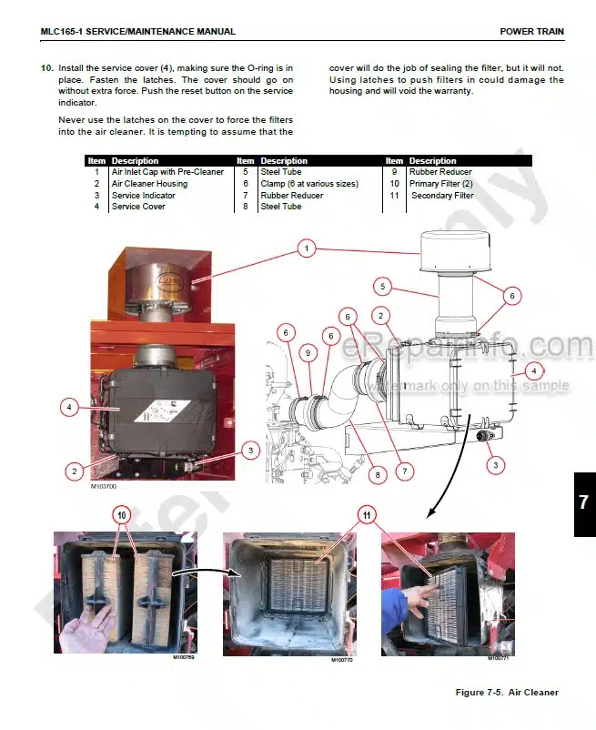
Engine Air Cleaner Maintenance
Engine Clutch Adjustment
Engine Throttle Adjustment
Hydraulic Power Generator
Power Plant Fuel System
Power Plant Cooling System
Mobile Power Washing
Fire Suppression System
Storage and maintenance Access Panels
Section 7 Inserts
-UNDER CARRIAGE
Travel System Operation
Travel diagnostic display
travel electrical schematic
Crawler Adjustment
-VARIABLE POSITION COUNTERWEIGHT (VPC)
General
VPC Component Identification
VPC System Diagnostics Overview
VPC Electrical Schematic
VPC EXT/RET Limit Switch
VPC Secured Limit Switch
VPC Assist Cylinder Cradle Limit Switch
VPC Actuator Seated in the Mast Raising Frame
Pivot Frame Actuator Catch Assembly
Counterweight Beam Limit Switch
VPC Angle Sensors
-ACCESSORIES
Accessory System Components
Operator Cab Heater
What you get
You will receive PDF file with high-quality manual on your email immediately after the payment.


Reviews
There are no reviews yet.