Repair Manual For New Holland T5000 series. Illustrations, instructions, diagrams for step by step remove and install, assembly and disassembly, service, inspection, repair, troubleshooting, tune-up.
Format: PDF
Language: English
Pages: 1752
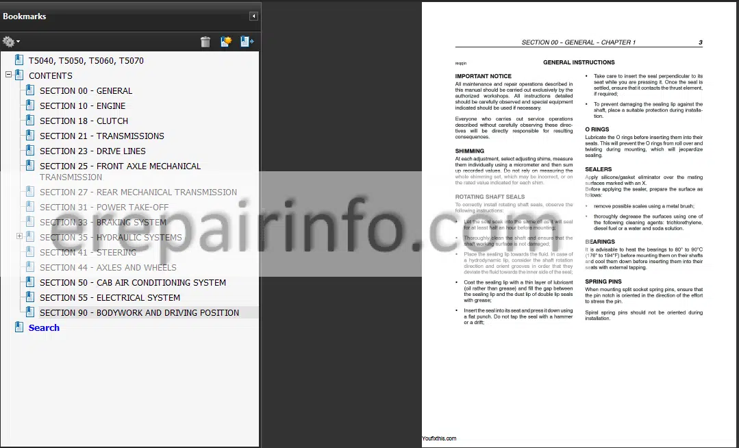
Bookmarks: Yes
Searchable: Yes
Number: 84195947; 84195945
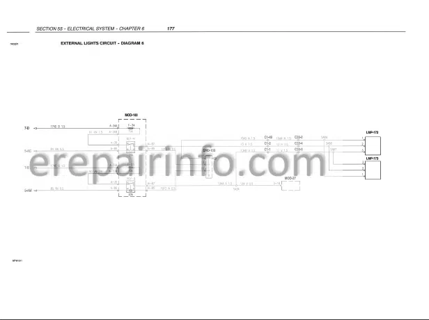
Wiring Diagrams: Yes
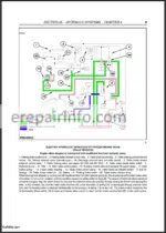
Hydraulic Diagrams: Yes
Model
New Holland T5040, T5050, T5060, T5060
Contents
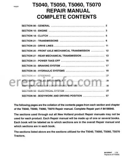
- – General
General Instructions
Health And Safety
Precautionary Statements
Safety
Ecology And The Environment
Minimum Hardware Tightening Torques
Federal Emissions Warranty
California Emission Control Warranty Statement
Consumables - – Engine
Crankshaft Front Seal
Crankshaft Rear Seal
Valve Tappet And Rocker Arm Clearance
Engine Injector
Bosch Injection Pump
Injector Pump
Bosch Injection Pump
Fuel Circuit Air Bleeding
Coolant Pump
Thermostat Valve
Radiator
Coolant Pump And Generator Drive Belts
Adjusting Tension - – Clutch
Longitudinal Section OfLuk Clutch
Electrohydraulic Power Take Off
Longitudinal Section OfLuk Clutch
Mechanical Power Take Off
Longitudinal Section Through Flexible Coupling
Power Shuttle Unit
Troubleshooting
Checks, Measurements And Repairs
Dual Clutch
Main Transmission Clutch Release
Adjustment
Test Bench Overhaul And Adjustment
Coplanarity Adjustment Of Dual Clutch Release Levers
Single Disk Clutch - – Transmissions
Transmission Diagrams
Torques
Clutch Reverser Casing - – Drive Lines
Electro-Hydraulically Engaged Drive Gear
Services Control Valve
Services Control Valve (For Tractors Without Power Shuttle)
Drive Gear Assembly
Drive Gear Housing Removed - – Front Axle Mechanical Transmission
LimSlip SelfLocking Differential Operation
Front Differential Lock
Rules For Correctly Installing The Axle Support To The Engine
Front Axle
Front Axle Differential
Front Axle Differential With Lim Slip Unit
Front Axle Differential Lock Clutch Assembly
Front Epicyclic Final Drive Without Brake
Front Epicyclic Final Drive With Brake
Wheel Hub Seal With Brake
Stub Axle Adjustments
Pinion And Crown Wheel Adjustments
Adjusting The Bevel Pinion Shaft Bearing Preload With Shims
Adjusting The Bevel Crown Wheel Bearings And Checking The Clearance Between The Sides Of The Bevel Drive Teeth - – Rear Mechanical Transmission
Hydraulically Controlled Rear Differential Lock
Rear Gearbox Transmission Casing
Gearbox Transmission Casing
Gearbox Driving Shaft End Float Adjustment
Adjusting The Position Of Differential Lock Engagement Sleeve
Pinion And Crown Wheel Adjustments
Determining The Bevel Pinion Positioning Adjustment Ring
Adjusting The Bevel Gear Pair
Tapered Roller Bearings Adjustment For Pinion Shaft
Adjusting The Bevel Crown Wheel Bearings And Checking The Clearance Between The Bevel Drive Teeth
Bevel Drive Adjustments
Adjusting The Preloading On The Bevel Drive Bearings
Adjustment Of The Clearance Between The Sun And Planet Pinion Teeth
Differential Lock Control Pedal Stroke
Adjustment
Final Drive Casing
Epicyclic Final Drive
Drive Wheel Shaft - – Power TakeOff
Mechanical Pto
Pto Controlled Directly From The Engine Clutch
Pto Synchronized With Gears
Selecting The Speed With The Lever
Cooling System
Power TakeOff Housing
Mechanical Power TakeOff Shafts - – Braking System
Service Brakes
Service Brake On Front Axle
Parking Brake
Pilot Valve Operation
Brakes At Rest
Braking Applied On Just One Pedal
Braking Applied On Both Brake Pedals
Hand Brake Control
Travel Adjustment
Parking Brake Casing
Brakes Hydraulic System
Air Bleed
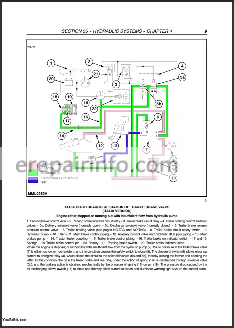
Tractor Equipped With Hydraulic Trailer Braking Valve
Tractor Equipped With Braking On The Front Axle
Tractor Equipped With Pneumatic Trailer Braking Valve
Service Brake Pump
Adjusting The Height Of The Service Brakes Pedals
Right Or Left Brake - – Hydraulic Systems
Hydraulic Lift Circuit
Arm Lift Phase
Neutral Phase
Arm Lower Phase
Lift Oil Pump
Fast Raise/Lower Control
Linkage Adjustments
Position Control Rod Adjustments
Draft Control Rod Adjustments
Fast Raise/Lower Device Adjustments
Adjustment Of The Upper Stroke Limit Of The Fast Raise/Lower Device
Rear Lift External Controls
Rear Lift
Rear Hydraulic Lift
Lift Adjustments
Adjusting Position Control
Lift Arms Maximum Raise Position Adjustment
Adjusting Draft Control
Lift Control Valve
Lift Pressure Relief Valve - – Steering
Balancing Valve Components
Neutral Position
Steering To Right
Steering To The Left
Manual Turning To The Right
Manual Turning To The Left
Hydrostatic Steering Control Valve
Hydrostatic Steering Control Valve With Control Valve Removed
Hydrostatic Steering Control Valve
Bench Test
Checking Rotating Valve Wear
Checking Return To Neutral Position
Seal Check
Pressure Relief Valve Calibration
Checking The Hydrostatic Steering Pressure Relief Valve With
Control Valve Installed On Tractor
Power Steering Oil Pump
Front Axle Steering Cylinder - – Axles And Wheels
Front Wheel Track Diagram
Torques
Sectional Views
Front Axle Hub
Front Axle
Stub Axle
Checking Wd Front Wheel Camber And ToeIn
Checking Wd Front Wheel Alignment - – Cab Air Conditioning System
Main Components Of The Air Conditioning System
Compressor
Condenser
Receiver/Dryer
Thermostatic Expansion Valve
Thermostatic Switch Defrost
Evaporator
Cab Heating And Ventilation Controls
Ventilation
Electric Fan
Air Filter
Heating
Temperature Control Knob ()
Ignition Switch
Cab Air Conditioning Controls
Air Conditioning And Temperature Control Knobs
Heater Control Knob
Electric Fan Control Knob
Instructions For Use
Start-Up
Adjustment
Switching Off
Air Conditioning System Recovery Recycling Evacuation Charging Station
Meaning
Checking For Refrigerant Leaks Using An Electronic Leak Detector
Refrigerant Gas Leak Test
Maintenance
Maintenance Of The Air Conditioning System
Troubleshooting
Visual Inspection Of Components
Checks And Adjustments
Functional Tests
Checking The Temperature Of The Air Coming Out Of The Vents Inside The Cab
Variations In Working Temperatures Of The Cab Air Conditioning System
Checking For And Eliminating Any Gas Leaks
Compressor Drive Belt
Fitting The Compressor Drive Belt
Tension Adjustment
Periodic Checking Of Drive Belt
Air Conditioning Compressor
Compressor Oil
Type And Quantity
Heating Pipes
Air Conditioning Pipes
Air Conditioner Condenser
Cab Heating Unit
Air Conditioner Evaporator
Electric Fan - – Electrical System
Standard Dashboard
Analog/Digital Instrumentation Panel
Instruments
Rev Counter
Engine Coolant Temperature Indicator
Fuel Level Indicator
Liquid Crystal Displays
Clock
Central Display
Ground Speed Display
Information Monitor
Setting And Resetting The Hours Worked
Resetting Hours Worked
Setting Hours Worked On A New Dashboard
Brightness Control
Access To The “Setup Menu” Via Keypad
Manual Calibration
Automatic Forward Speed Calibration
Hour System Clock Setting
Speed Unit Of Measurement Setting
Beep Setting
Implement Width Setting
Slip Percentage Setting
Heavy/Light Maintenance Setting
Access To The “Warnings Not Displayed” Menu
Warnings Of A Critical Nature
Warnings Of A NonCritical Nature
Calling Up Functions From Keypad
Area Worked
Area Per Hour
Odometer
Maintenance Periods
Hours Worked, Air Brake Pressure Brake And Battery Charge
Wheel Slip And Power TakeOff Speed
Rear Implement Position
Access To The “Setup Menu” With The Cal Button
Calling Up Functions With The Cal Button - – Bodywork And Driving Position
Hood
Platform
Driver’s Seat
Cab
Cab RightHand Or LeftHand Door
Glued Cab Windshield
Fitting The Window
Cab Rear Windshield
Seal On Lh Upright
Strip On Rh Upright
Fixed Padding On Rh Wall
Fixed Padding On Lh Wall
Hydraulic Control Lever Guard
Cab Ceiling Fitting
What you get
You will receive PDF file with high-quality manual on your email immediately after the payment.

Reviews
There are no reviews yet.