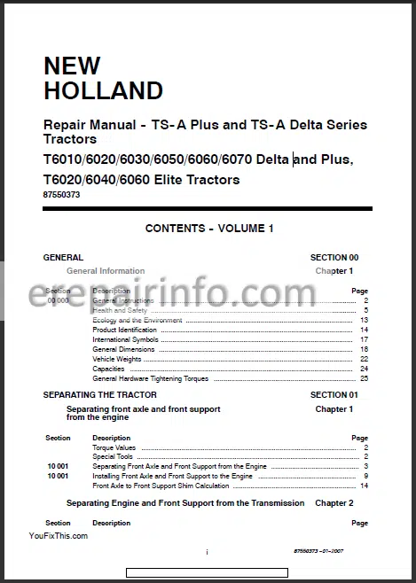
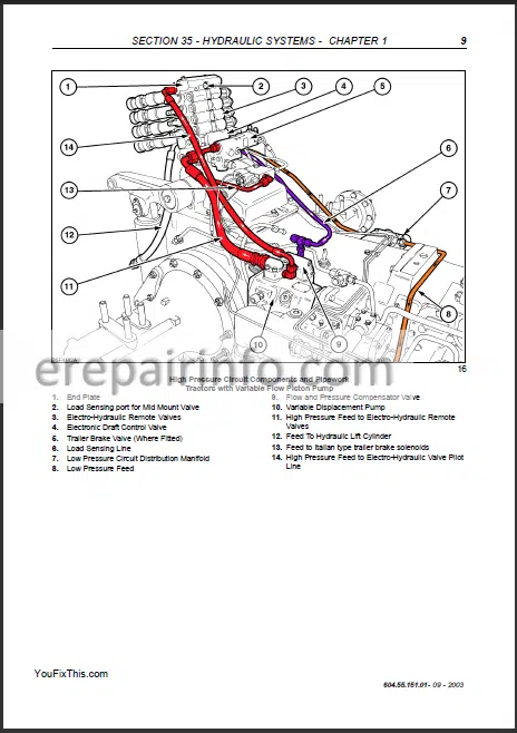
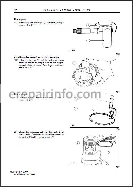
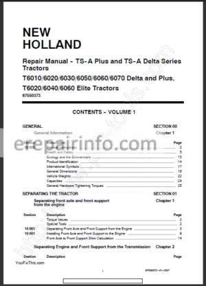
Repair Manual For New Holland T6000 series Tractors. Illustrations, instructions, diagrams for step by step remove and install, assembly and disassembly, service, inspection, repair, troubleshooting, tune-up.
Format: PDF
Language: English
Pages: 4423
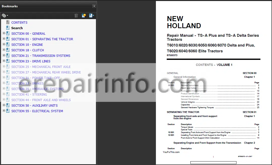
Bookmarks: Yes
Searchable: Yes
Number: 87550373
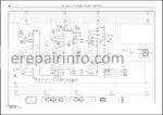
Wiring Diagrams: Yes
Hydraulic Diagrams: Yes
Model
New Holland T6010, T6020, T6030, T6040, T6050, T6060, T6070
Contents
- – General
General Instructions
Health And Safety
Ecology And The Environment
Product Identification
International Symbols
General Dimensions
Vehicle Weights
Capacities
General Hardware Tightening Torques - – Separating The Tractor
Separating Front Axle And Front Support From The Engine
Installing Front Axle And Front Support To The Engine
Front Axle To Front Support Shim Calculation - – Engine
Cooling System
Lubrication System
Lubrication System Components
Engine Overhaul
Bushings
Assembly On The Workbench
Fitting Engine Components
Checks, Dimensions And Repairs (Cylinder Liner Block)
Checks, Dimensions And RepairsCrankshaft, Bearings
Timing System
Bushings
Checks, Dimensions And RepairsPistons
Connecting RodPiston Assembly
Valves
Valve Guides
Valve Seats
Valve Springs
Fitting The Cylinder Head
Fuel Supply Gear Pump
Cp High-Pressure Pump
Rail (Pressure Accumulator)
Pressure Relief Valve
Electro Injector
Pressure Limiter For Fuel Return - – Clutch
Hydraulic Release Bearing / Slave Cylinder - – Transmission Systems
Fault Finding Diagrams
Front Section
Middle Section
Rear Section
Transmission Top Cover
Transmission Control Valve
Synchronizer Inspection
Transmission Housing Transfer Tubes
Forward/Reverse Synchronizer EndFloat Adjustment
Adjustment Of Forward/Reverse And Main Synchronizers
High/Low Range Cable Adjustment
Adjustment Of The High/Low Synchronizer - – Drive Lines
Standard Front Axle Four Wheel Driveshaft
Standard Front Axle Four Wheel Driveshaft
Four Wheel Drive Clutch
Four Wheel Drive Multi–Wet Plate
Four Wheel Drive Dog Clutch
Four Wheel Driveshaft Oil Supply Manifold - – Mechanical Front Axle
Standard Axle
Hub Cassette Seal
Front Axle Overhaul All Options
Multi Wet Plate Clutch Differential
Crown Wheel / Differential
Multi Wet Plate Clutch Differential Lock
Crown Wheel / Differential
MultiWet Plate Clutch Differential Lock
Dog Clutch Differential Lock
Crown Wheel / Differential
Dog Clutch Differential Lock
Pinion Shaft
Crown Wheel AdjustmentsMultiWet Plate Clutch Differential Lock
Differential Bearing PreloadMultiWet Plate Clutch Differential Lock
Crown Wheel AdjustmentsDog Clutch Differential Lock
Differential Bearing PreloadDog Clutch Differential Lock
Limited Slip Self Locking Differential
Axle AssemblyAll Options
Swivel Pin & Potentiometer
Checking the Alignment of Steering & Drive Wheels - – Mechanical Rear Wheel Drive
Rear Axle
Rear Pinion and Crown Wheel
Hydraulic Pump Idler Gear Bearing Adjustment
Hydraulic Differential Lock Control Unit
Final Drive Case (Left or Right Hand)
Drive Wheel Shaft - – Power TakeOff
Rpm Pto Sectional View And Torque Values
Rpm Pto Sectional Views And Tightening Values
Pto Functionality
Fault Finding
Power Take Off
Speed Shaft Change Pto - – Brakes
Fault Finding
Rear Service Brake Piston (Left Or Right Hand)
Rear Service Brake Inspection
Rear Service Brake Piston (Left Or Right Hand)
Front Service Brake Valve
Front Service Brake (Left Or Right Hand)
Hydraulic Brake Master Cylinder
Hydraulic Brake System Air Bleeding
Front Service Brake Valve Removal Models With Integrated Front Lift
Front Service Brake Valve Installation Models With Integrated Front Lift
Brake Pedal Switch
Brake Pedal Linkage Adjustment
Brake Pedal Switch Adjustment
Parking Brake
Parking Brake Cable Adjustment
Additional Information Brake Overhaul - – Hydraulic Systems
Variable Displacement Pump High Pressure Hydraulic Circuits
Fixed Displacement Pump High Pressure Hydraulic Circuit
Low Pressure Hydraulic Circuits
General Hydraulic Fault Finding
Initial Fault Finding Check
Transmission Low Pressure Warning Light ‘On’
Charge Pressure Light
Intake Filter Restriction Warning Light
Power Steering
Trailer Brakes
Hydraulic Lift
Remote Control Valves - – Steering
Steering Motor
Steering Column
Two Wheel Drive Steering Cylinder
Two Wheel Drive Steering Cylinder - – Front Axle And Wheels
Front Axle
Front Wheel Hub and Spindle Assembly
Spindle
Front Wheel Settings
Wheel Camber Tests
Track Width Adjustment
Axle Centre Beam and Front Support
Front Wheel Toein alignment (Standard Axle) - – Auxiliary Units
Safety Precautions
Description And Operation
Fault Finding And System Testing
Leak Testing, Charging, Discharging And System Flushing
Flushing The System
Evacuating The System
Charging The System
Compressor - – Electrical System
Electrical System And Fuses Description
Fuses And Relays
Controllers
Diagnostic Connectors
System Precautions For Battery Charging And Welding
Temporary Wiring Repair
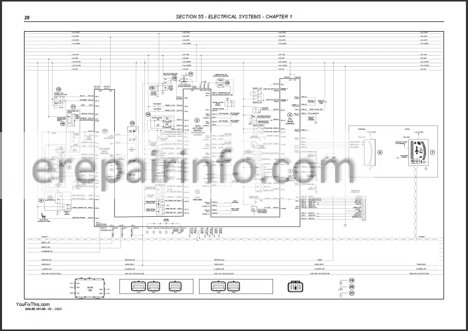
System Diagrams
What you get
You will receive PDF file with high-quality manual on your email immediately after the payment.


Reviews
There are no reviews yet.