Factory Service Manual For New Holland Wheeled Excavator. Manual Contains Illustrations, Instructions, Diagrams For Step By Step Remove And Install, Assembly And Disassembly, Service, Inspection, Repair, Troubleshooting, Tune-Ups.
Format: PDF
Language: English
Pages: 860
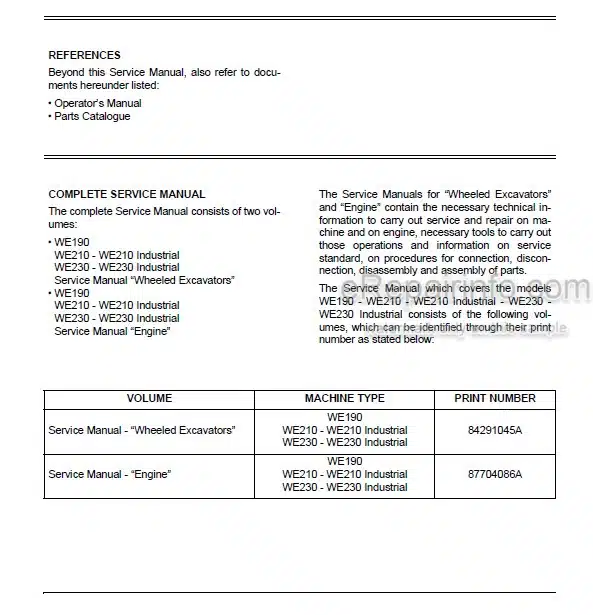
Number: 84291045A
Bookmarks: Yes
Searchable: Yes
Wiring Diagrams: Yes
Hydraulic Diagrams: Yes
Model
New Holland Wheeled Excavator
WE190
WE210
WE210 Industrial
WE230
WE230 Industrial
Contents
– SAFETY PRECAUTIONS
Introduction
General Safety Instructions
Use Instruction
– CONTROLS AND INSTRUMENTS
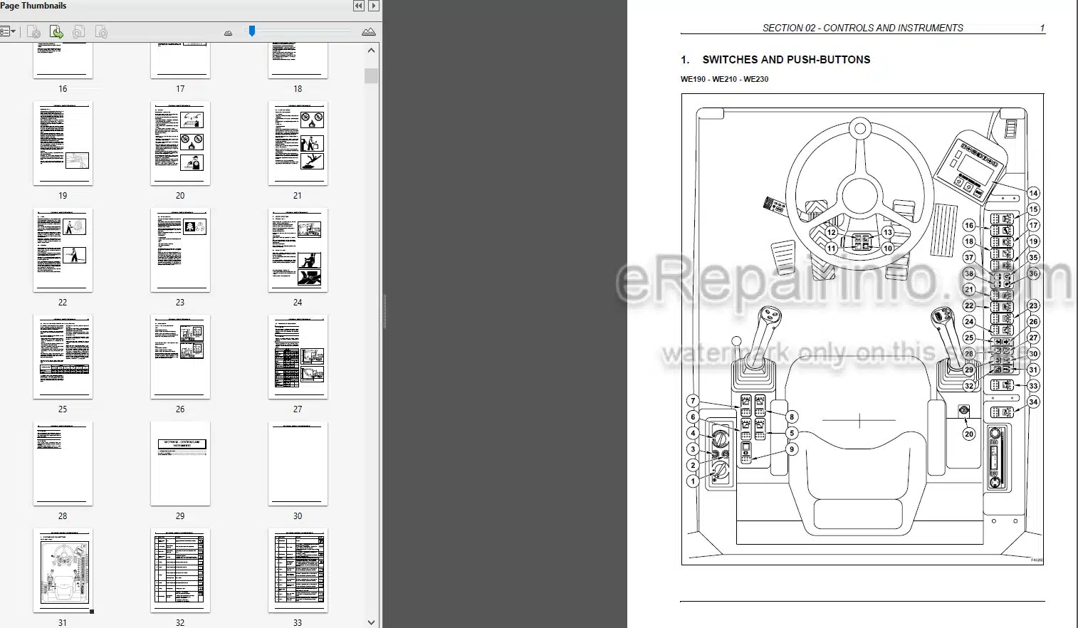
Switches And Push-Buttons
Controls And Pedals
Multi-Function Display
– TECHNICAL SPECIFICATIONS
Main Components
Dimensions – Operating Weights
Digging Performance
Lifting Capacities
Hydraulic System
Slewing
Travel Brakes
Steering
Electrical System
Tightening Torques
Fuel System
Engine
Supply Summarizing Chart
– UPPER STRUCTURE
Main Components
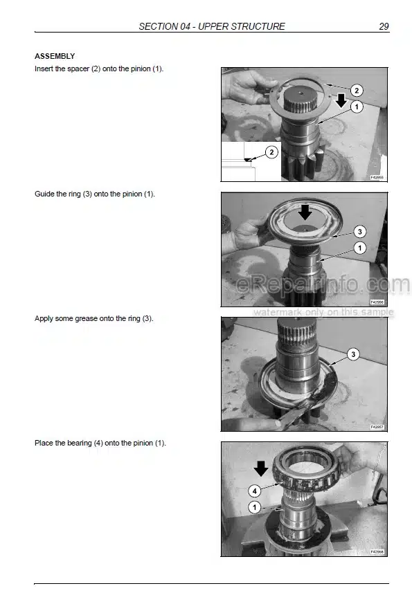
Slewing Bearing
Slewing Gearbox
Multi-Cooler
Hydraulic Pumps
Muffler
Hydraulic Oil Tank
Air Filter
Counterweight
Fuel System
Cab And Operator’S Seat
Centralized Lubrication
– UNDERCARRIAGE
Undercarriage Components
Rear Rigid Axle
Travel Motor
Cardan Shaft
Front Steering Axle
Wheels And Tyres
Blade
Axle Floating Locking Cylinders
Stabilizers
Left Ladder
Right Ladder And Tool Storage Box
Rotary Control Valve And Electric Rotor
– FRONT ATTACHMENT
Types Of Front Attachment
Hydraulic Cylinders
Buckets
– STEERING SYSTEM
Operation
Power Steering
Priority Valve
Troubleshooting
– BRAKE SYSTEM
Operation
Service Brake
Parking Brake
Pedal Brake Valve
Accumulators
Troubleshooting
– HYDRAULIC SYSTEM
Hydraulic System
Hydraulic System Diagrams
Hydraulic Pumps
Upper Structure Control Valve
Undercarriage Control Valve
Pilot Control Assy
Rotation System
Travel
Stabilization Hydraulic System
Boom Hydraulic System
Hydraulic System Of Bucket
Hydraulic System Of Dipper
Hydraulic System Of 2-Piece Boom
Hydraulic System With Combination Of Different Functions (Boom, 2-Piece Boom, Dipper And Bucket)
Hydraulic System Of Hammer (With 2-Piece Boom)
Hydraulic System Of Hammer And Shears (With 2-Piece Boom)
Hydraulic System Of Shears (With 2-Piece Boom)
Hydraulic System Of Hammer (With Monoboom)
Hydraulic System Of Hammer And Shears (With Monoboom)
Hydraulic System Of Shears (With Monoboom)
Troubleshooting
– ELECTRICAL SYSTEM
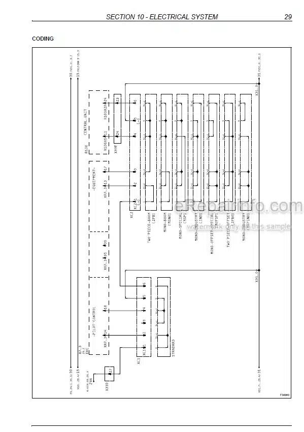
Electrical Diagrams
Fuses
Bulbs
– ELECTRONICS
Main Components
Components Of Line 1
Components Of Line Can 2
Engine Speed Actuator
Coolant Temperature Detection
Charge Air Temperature Detection
Hydraulic Oil Temperature Detection
Proportional Valve – Fan Motor
Proportional Valves – Control Block
Pilot Control Block
– CALIBRATION
Necessary Operations Before Calibration
Display: Calibration Menu
Calibrations With The Engine Running
Calibrations With The Engine Stopped
– FAULT CODES
Error Indication On The Display
Central Unit And Engine
Pcs Unit (Power Control System)
Hydraulics
What you get
You will receive PDF file with high-quality manual on your email immediately after the payment.

Reviews
There are no reviews yet.