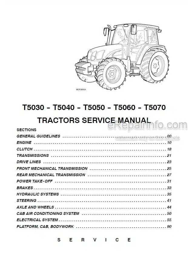
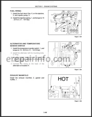
Factory Service Manual For New Holland Tractor. Manual Contains Illustrations, Instructions, Diagrams For Step By Step Remove And Install, Assembly And Disassembly, Service, Inspection, Repair, Troubleshooting, Tune-Ups.
Format: PDF
Language: English
Pages: 1752
Number: 87679925A
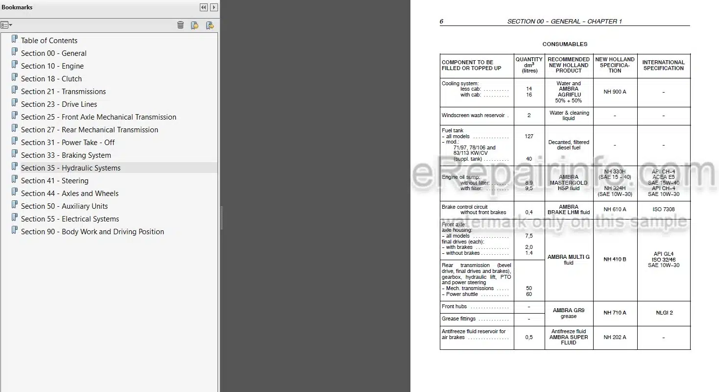
Bookmarks: Yes
Searchable: Yes
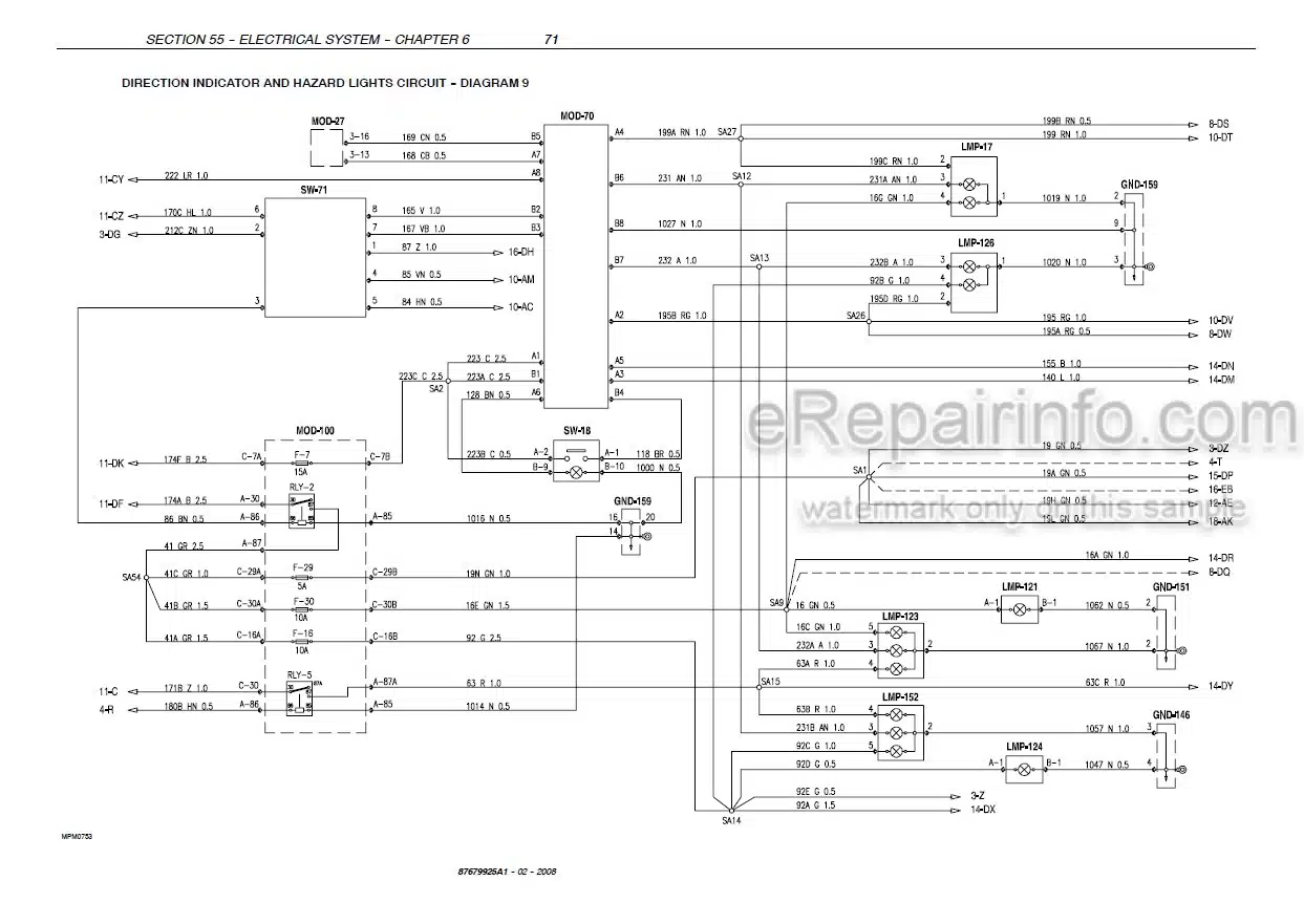
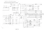
Wiring Diagrams: Yes
Hydraulic Diagrams: Yes
Model
New Holland Tractor
T5030
T5040
T5050
T5060
T5070
Contents
-GENERAL GUIDELINES
General Instructions
Safety Regulations
Tractor Refuelling
– ENGINE
Summary
General Specifications
Fuel System Data
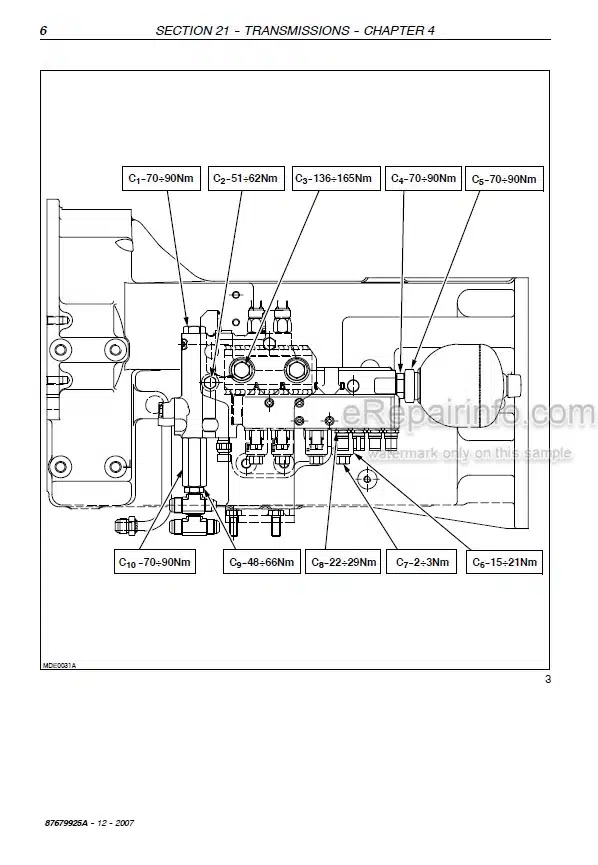
Torque Specifications
Special Tools
View Of 4-Cylinder Engine Fault Diagnosis
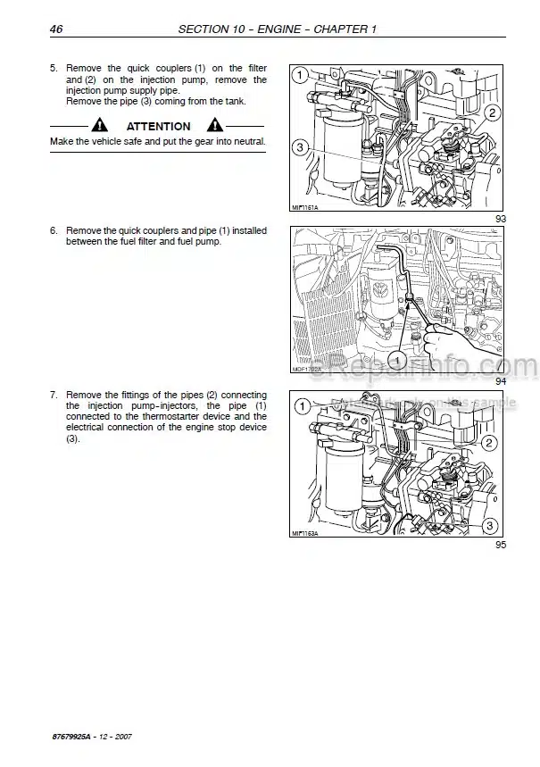
Engine Removal-Installation
Replacing Crankshaft Front Seal
Replacing Crankshaft Rear Seal
Adjusting Tappet, Valve And Rocker Arm Clearance
Removal-Installation – Injectors
Removal – Installation -Bosch Injection Pump
Injection Pump, Renewal And Checking Timing
Bosch Injection Pump – Air Bleeding
Removal-Installation Coolant Pump
Removal-Installation Thermostat Valve
Removal-Installation – Radiator
Coolant Pump Drive Belt Adjustment
-CLUTCH
Summary
Main Data
Torque Specifications
Special Tools
Sections
Fault Diagnosis
Checks And Measurements – Clutch
Adjustments – Clutch Pedal
Removal -Installation Clutch
Clutch Overhaul
Adjustments – Clutch Disengagement Levers
-TRANSMISSIONS
Reverser
Reverser And Creeper Unit
Power Shuttle Transmission (12X12)
Power Shuttle Transmission With Dual Command (2 Speed Power Shift) Function
Power Shuttle Transmission With Creeper Unit – 20X20 Version
-DRIVE LINES
Summary
Main Data
Torque Specifications
Special Tools
Sections
Description And Operation
Fault Diagnosis
Removal-Installation – Services Control Valve
Disassembly-Assembly -Services Control Valve
Removal -Installation
Drive Gear Casing
Disassembly-Assembly -Drive Gear Casing
-FRONT AXLE MECHANICAL TRANSMISSION
Summary
Main Data
Torque Specifications
Special Tools
Sections
Description And Operation
Fault Diagnosis
Rules For Correctly Fitting The Axle Support To The Engine
Removal-Installation Front Axle
Disassembly-Assembly -Front Axle
Overhaul – Front Differential
Overhaul – Front Axle Differential With Lim-Slip
Overhaul – Differential Lock Unit
Disassembly-Assembly -Front Epicyclic Final Drive Without Brake
Disassembly-Assembly -Front Epicyclic Final Drive With Brake
Replacing Wheel Hub Seal With Brake
Stub Axle Adjustments
Adjustments – Bevel Drive
-REAR MECHANICAL TRANSMISSION
Summary
Main Data
Torque Specifications
Special Tools
Sections
Description And Operation
Fault Diagnosis
Removal-Installation – Transmission-Gearbox Casing
Disassembly-Assembly -Transmission-Gearbox Casing
Gearbox Driving Shaft End Float Adjustment
Adjustments – Differential Lock Engagement Sleeve Position
Determining The Bevel Pinion Positioning Adjustment Ring
Tapered Roller Bearings Adjustment For Pinion Shaft
Adjusting The Bevel Crown Wheel Bearings And Checking The Clearance Between The Sides Of The Bevel Drive Teeth
Adjusting The Preloading On The Bevel Drive Bearings
Differential Pinion And Side Gear Backlash Adjustment
Differential Lock Pedal Travel Adjustment
Removal-Installation – Final Drive
Disassembly-Assembly -Epicyclic Final Drive
Disassembly-Assembly -Drive Wheel Shaft
-POWER TAKE–OFF
Summary
Main Data
Special Tools
Torque Specifications
Sections
Description And Operation
Fault Diagnosis
Fitting Cooler With Mechanical Transmission And Power Take-Off
Cooling System Description And Operation
Removal-Installation -Power Take-Off
-BRAKES
Summary
Main Data
Torque Specifications
Sections
Description And Operation
Hydraulic Diagram -Brakes
Pilot Valve Operation
Fault Diagnosis
Adjustments – Parking Handbrake Travel
Removal-Installation/Disassembly-Assembly Parking Brake Casing
Service Brake Circuit Air Bleeding
Removal-Installation – Service Brake Pump
Adjusting The Height Of The
Service Brake Pedals
Removal-Installation – Service Brake
-TRAILER AIR BRAKES (ITALIAN AND GERMAN VERSION)
Summary
Main Data
Torque Specifications
Special Tools
Sections
Description And Operation
Operation Of Single Trailer Brake Circuit Components
Fault Diagnosis
Pressure Tests
-HYDRAULIC SYSTEMS
Rear Mechanical Hydraulic Lift
Open Centre System Auxiliary Control Valves
Auxiliary Control Valves (BOSH)
Trailer Brakes Auxiliary Control Valves
Supplementary Cylinder
-STEERING
Data
Tightening Torque
Components And Operating Diagrams
Troubleshooting
Tools
Power Steering Control Valve R L
Power Steering Control Valve D A
Power Steering Control Valve Bench Testing
Power Steering Oil Pump D. A.
Front Axle Steering Cylinder R. L.
Front Axle Steering Cylinder R. L.
-AXLES AND WHEELS
Data
Sections
Tightening Torque
Fault Diagnosis And Equipment
Front Axle Hub D. A.
Front Axle R. L.
Stub Axle Overhaul
Checking 2 WD Front Wheel Camber And Toe-In
Checking 4 WD Front Wheel Alignment
-AUXILIARY UNITS
Safety Regulations
General Specifications
Tools
Operating Principles
Main Components Of The Cab Air Conditioning System
Warnings For Air Conditioning System Repair Operations
Cab Controls
Instructions For Use – Air Conditioning System
Refrigerant Recovery – Recycling And Evacuation – Charging Stations
Electronic Leak Detector 380000314
Air Conditioning System Maintenance
Air Conditioning System Troubleshooting
Air Conditioning System Troubleshooting
Air Conditioning System Functional Testing
Checking For Gas Leaks With Leak Detector 380000314
Compressor Drive Belts
Compressor Drive Belts Tension Adjustment
Air Conditioner Compressor R. L.
Heating Pipes Renew
Air Conditioning Pipes Renew
Air Conditioner Condenser Renew
Filter/Dryer Renew
Cab Heater Unit R. L.
Air Conditioner Evaporator Renew
Electric Cab Fan R. L.
-ELECTRICAL SYSTEM
Instrument Panel
Components
Starting System
Charging System
Battery
Electrical Circuits
Wiring Harnesses And Connectors
Components
Fault Codes
HH Menu And Calibrations
-BODYWORK AND DRIVING POSITION
Removing Components
What you get
You will receive PDF file with high-quality manual on your email immediately after the payment.

Reviews
There are no reviews yet.