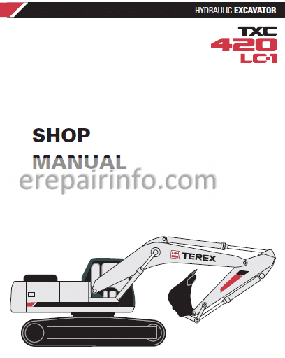
Factory Service Repair Manual For Terex Terex TXC420 LC1 Hydraulic Excavator. Tons of illustrations, instructions, diagrams for step by step remove and install, assembly and disassembly, service, inspection, repair, troubleshooting, tune-ups.
Format: PDF
Language: English
Pages: 607
Bookmarks: Yes
Searchable: Yes
Wiring Diagrams: Yes
Hydraulic Diagrams: Yes
Model
Terex TXC420 LC1
Contents
– Safety
To the Operator of a TEREX Excavator
General Safety Essentials
Location of Safety Labels
Summary of Safety Precautions for Lifting in Digging Mode
Unauthorized Modifications
General Hazard Information
Before Starting Engine
Machine Operation
Maintenance
Battery
Towing
Shipping and Transportation
Lifting With Sling
Track Excavator Safety
– Specifications
General Description
Component Locations
General Dimensions
Dimensions and Working Range
General Specifications
Engine Performance Curves (Per KS-R1004 Standard)
Approximate Weight of Workload Materials
Performance Tests
Excavator Performance Standards
Test Conditions
Travel Speed and Travel Motor Balance (Steering Deviation) Tests
Swing Speed and Deceleration Force Test
Cylinder Performance Tests
– General Maintenance
Welding Precautions and Guidelines
Hydraulic System – General Precautions
Maintenance Service and Repair Procedure
General Precautions
Hydraulic System Cleanliness and Oil Leaks
Maintenance Precautions for Hydraulic System Service
Oil Leakage Precautions
Cleaning and Inspection
General Guidelines
Bearing inspection
General Maintenance Procedures
Standard Torques
– Upper Structure
Removal
Installation
Cab
Counterweight
Fuel Tank
Fuel Transfer Pump
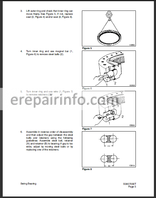
Swing Bearing
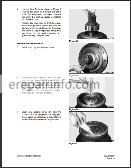
Swing Reduction Gearbox
– Lower Structure and Chassis
General Description
Track Tension
Cleaning and Inspection (Wear Limits and Tolerances)
Track Shoes and Links
Parts List
Track Removal
Track Installation
Front Idler Roller
Parts List
Front Idler Roller Disassembly
Front Idler Roller Reassembly
Lower Roller
Parts List
Lower Roller Removal
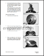
Lower Roller Disassembly
Lower Roller Reassembly
Lower Roller Installation
Upper Roller
Upper Roller Removal
Upper Roller Disassembly
Upper Roller Reassembly
Track Spring and Track Adjusting Cylinder
Track Assembly
– Engine and Drive Train
General Description
Refrigerant Circulation
Control Panel
Control Specifications
Temperature Level Control and Display
Air Discharge According to Path Selection
Air-conditioning System Circuit Diagram
Troubleshooting
Weight of R134a Gas Used In Machines
Refrigerant System Repairs
Refrigerant Safe Handling Procedures
Repair and Replacement Procedure
Refrigerant Recovery
Vacuuming Refrigerant System
Leakage Check
Refrigerant Charging
Inspecting System For Leakage
Air-Conditioner
Drive Coupling (Main Pump)
– Hydraulics
Hydraulic System Troubleshooting, Testing and Adjustment
Accumulator
Center Joint (Swivel)
Cylinders
Swing Motor
Travel Motor (with Gearbox) (Nabuko)
Main Pump (Rexroth)
Control Valve
Pilot Control Valve (Work Lever / Joystick)
Travel Control Valve (With Damper)
Hydraulic Schematic
– Electrical System
Troubleshooting – Electrical System
Overview
Electric Supply System
Engine Starting Circuit
Operation During Start Process
Operation After Start Process
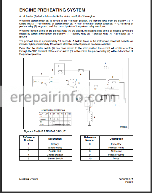
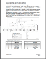
Engine Preheating System
Engine Stop System
Charging System
Monitoring System
Instrument Panel
Monitoring System Schematic
Operation
Instruments
Warning and Indicator Lights
Initial Operation
Mode Select Switch
Graphic Information Area Display
Overview
Main Menus for the Graphic Display Area
Menu Selection Buttons
Main Menu
Language setting
Time Setting
Filter/Oil information
Special Menu
Entering/Accessing and Exiting/Escaping Menus
Special Menu Selections
Electronic Hydraulic Control System (e-EPOS)
Control System Schematic
Power Mode Control
Operation
Power Mode Control – Circuit Diagram
Trenching Mode Control
Operation
Trenching Mode Control – Circuit Diagram
Engine Control System
Engine Control Motor
Engine Control Dial
Engine Control Circuit Diagram
Automatic Deceleration Control (Auto Idle Control)
Engine Overheat Protection System
Power Boost Mode
Operation
Power Boost Control – Circuit Diagram
Automatic Travel Speed Control
Automatic Travel Speed Control – Circuit Diagram
Engine Control Device – Adjustment
Self-diagnostic Function
e-EPOS Controller
Engine Throttle Controller
Wiper System
Wiper Circuit
Wiper Operation
Window Washer Operation
Lighting System
Lighting System Circuit Diagram
Kind of Light
Operation
Overload Warning Device
Overload Warning Device Circuit Diagram
Electrical Schematic
– Attachments
Front Attachment Pin Specifications
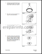
Front Attachment – Removal and Installation
Arm Removal Procedure
Boom Removal Procedure
Installation
Arm Installation Procedure
Boom Installation Procedure
Start-up Procedures
Boom and Arm
Bucket
What you get
You will receive a PDF file with high-quality manual(s) on your email immediately after the payment.

Reviews
There are no reviews yet.