


Factory Service Manual For Tigercat Feller Buncher. Manual Contains Illustrations, Instructions, Diagrams For Step By Step Remove And Install, Assembly And Disassembly, Service, Inspection, Repair, Troubleshooting, Tune-Ups.
Format: PDF
Language: English
Pages: 198
Number: 9725A (december 2003)
Bookmarks
Searchable
Wiring Diagrams
Hydraulic Diagrams
Model
Tigercat Feller Buncher
845B
Contents
INTRODUCTION
NON-APPROVED FIELD PRODUCT CHANGES
-SAFETY
Battery Disconnect Switch
Cab Exits
Cooling System
Emergency Cab Exits
Engine Doors
Er Boom System
Exhaust Fumes
Felling Trees
Fire Prevention
First Aid
Fluid Leaks
Hydraulic Pressure Hazard
Loose Clothing Hazard
Parking Hazards
Protective Clothing
Safety Interlock Switches On Left Arm Rest
Safety Precautions. General
Safety Precautions, Operating
Safety Precautions, Servicing
Safety Symbols
Signal Words
-USING HIGH SPEED DISC SAWS SAFELY
Comments And Instructions
Dangers
Forward
High Angle Wrist Rotation Capability
Saw Head Don’ts
Type Of Housing Makes A Difference
-LUBRICATION & MAINTENANCE
Air Cleaner Maintenance
Air Conditioning System
Emergency Exits, Check Monthly
Engine Air Cleaner Maintenance
Filter And Lubrication Schedule
Filters
Fire Prevention Also See Section 1, Safety
General Maintenance
Hydraulic Oil Reservoir
Hydraulic Oils
Lubrication Schedule
New Machine Maintenance
Oil Lost From Leakage
Pressure Setting Procedures See Service Manual
Pressure Setting Values See Service Manual
Preventive Maintenance Schedule
Scheduled Maintenance
Swing Drive Gearbox Lubrication
Torque Chart, General
Torque Settings. Recommended
-HYDRAULIC SYSTEM
High Pressure Limiting Control Valve
Hydraulic Oil Reservoir
Hydraulic Oil Tank
Hydraulic Pumps
Hydraulic System Operation
Load Sensing
Main Control Valve/Manifold
Pressure Settings
Schematic Diagrams
-PILOT SYSTEM
Accumulator
Circuit Description
Circuit Diagram
Electrical Circuit
Pilot Supply Manifold
Pilot System Components
Pressure Settings
-ELECTRICAL, GAUGES AND ALARMS
Electrical Schematic Diagram (Earlier Machines)
Electrical Schematic Diagram (Later Machines)
Gauges And Alarms
Switch And Sensor Locations
Wire Color Code Chart
-ENGINE START AND STOP
Circuit Description
Engine Start Circuit
Schematic Diagram
-ENGINE ANTI-STALL
Control Module In Cab
Control Module Pin Connections
Engine Anti-Stall Curve
Fault Finding Procedure ~ Anti-Stall Quick Check
Fault Finding Procedures, Additional
Horsepower Limiting Control
Load Sense; Set Margin Pressure See Section 4
Main Pump Controller (LS Control)
Pilot Pressure, Set See Section 5
Schematic Diagrams
Speed Sensor, Adjusting
Speed Sensor On Engine
Verify Anti-Stall Setting See Section 4
-TRACK DRIVE
Drive Components, Assembly
Drive Motor
Drive Motor And Gearbox Assembly
Hydrostatic Drive System
Pressure Settings, Drive System
Schematic Diagrams
Track Components
Track Drive Notes, Important
Track Speed Set-Up
-BOOM FUNCTIONS
Adjust Oil Flow To Cylinders (Cylinder Cycle Times)
Boom Control Valve
Boom System Description
Circuit Schematic
Cylinder Cycle Times, Typical
Engine Anti-Stall
Load Sensing
Set Main Boom, Stick And Tilt Port Relief Valves
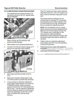
Tilt Cylinder (Rod End) Flow Adjustment
Tilt Cylinder Flow Adjustment
-SWING
Adjust Oil Flow To Swing Motor(Swing Motor Speed)
Lubricate Gearbox Lower Bearings
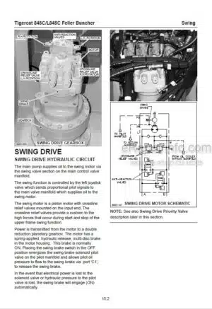
Schematic Diagrams
Set Swing Motor Speed
Swing Bearing Wear Limits
Swing Drive
Swing Drive Gearbox
Swing Motor Removal From Gearbox
-SAW DRIVE
Circuit Description
Circuit Diagram (Later Machines)
Circuit Diagram Earlier Machines)
Felling Head. See Original Manufacturers Manual
Filter, Case Drain
Pressure Settings
Saw Control Valves
Saw Pump
-TREE CLAMPS AND WRIST
Circuit Description
Circuit Diagram (Earlier Machines)
Circuit Diagram (Later Machines)
Control Valve
Pressure Settings
Pump:- Wrist, Tree Clamp And Accumulating Arms
Relief Valve. Anti-Cavitation
Wrist, 30°, 110° And 340°
What you get
You will receive PDF file with high-quality manual on your email immediately after the payment.


Reviews
There are no reviews yet