


Factory Service Manual For Tigercat Feller Buncher. Manual Contains Illustrations, Instructions, Diagrams For Step By Step Remove And Install, Assembly And Disassembly, Service, Inspection, Repair, Troubleshooting, Tune-Ups.
Format: PDF
Language: English
Pages: 730
Number: 54710AENG (september 2019)
Bookmarks
Searchable
Wiring Diagrams
Hydraulic Diagrams
Model
Tigercat Feller Buncher
845E
L845E
Serial Number 84513001–84513500
Serial Number 84523001–84523500
Contents
INTRODUCTION
-SAFETY
Backover Accidents-Avoiding
Battery Safety
Cab Exits
Cable Assist
ER Boom System
Escape Hatch, Roof
Felling Trees
Fire Prevention
Fluid Injection Injury
General Safety Precautions
Grease Injection Injury
Hazard Zone
Hydraulic Pressure Hazard
Interlock Switch, Safety
Lightning Safety Awareness
Liquid Starting Aid
Machine Stability And Traction
Notice Labels
Operating Safety Precautions
Parking The Machine
Pneumatic Grease Guns, Using
Protective Clothing
Refuelling
Safety Hazards-Operating
Safety Hazards-Viton Seals
Safety Interlock Switch, Cab Front Door
Safety Labels
Safety Precautions, General
Safety Precautions, Operating
Safety Precautions, Servicing
Safety Symbols
Seat Belt
Servicing And Repair
Servicing Safety Precautions
Signal Words
Synthetic Rubber Seal And Gasket Safety
Transporting The Machine
Viton Seals
Welding, Prior To
Working With Oil
-USING HIGH-SPEED DISC SAWS SAFELY
Comments And Instructions
Dangers
Foreword
Housing Types
Saw Head Do Nots
Type Of Housing Makes A Difference
-CONTROLS AND OPERATION
A/C/Defrost Switch
Air Source Switch
Alarm And Alarm Light
Attachment, Instructions And Precautions
Auxiliary Power And USB Ports
Battery Boosting
Battery Disconnect Switch
Belt Routing, Serpentine
Boom Controls
Cab Dome Light Switch
Cameras
Cold Weather Starting
Computer
Computer And Display
Computer Display(Home Screen)
Computer Display Messages
Control Panels
Control Pedals, Track Drive
Controls
Coolant Shut-Off Valves, Engine
Current Output Channels
Display, Camera Video
Electronic Device Holder
Emergency Exits
Engine Hot Coolant Shut-Off Valves
Engine Speed Switch
Engine, Stopping
ER Boom System, Instructions
Fan Service Mode
Fire Extinguisher, Cab
Fire Suppression System
Fuel, Refuelling Procedure
Fuel Tank
Heater Control Panel, Engine Coolant (Optional)
Horn/Safety Alert Switch
Hydraulic Oil Tank Vacuum Switch
Joystick Controls
Joystick Controls, Feller Buncher
Key Switch
Lights
Load Sensing, Operating Tips
Operating The Machine
Operating Tips: Load Sensing
Operation Modes
Operator’S Manual
Operator’s Seat
Pilot System Off Switch
Pilot System Reset Switch
Pilot System Safety Interlock Switch (Front Door)
Radio
Refuelling Procedure
Safety Interlock Switch (Front Door)
Saw Switch
Serpentine Belt Routing
Slope Indicators
Special Operating Instructions For ER Boom System
Starting And Stopping The Engine
Starting The Engine
Stopping The Engine
Storage Area
Swing Brake Switch
Switch
System Test And Warm Up
Telematics Repair Mode
Timed Purge Interval
Track Drive, Control Pedals
Track Drive Switch
Traveling
Traveling, Boom Raised
Travel Speed Adjuster
Video Display, Camera
Warm-Up Mode
Work And Service Lighting
-LUBRICATION AND MAINTENANCE
Aftertreatment System (Denox 22 System, Tier 4F)
Air Conditioning System
Air Filters
Air Intake System
Anti-Corrosion Spray, Removal, If Applicable
Anti-Seize Pastes, Approved For Exhaust/Aftertreatment Sensors
Battery Box Cover
Battery Care
Care Of The Machine
Case Drain Return Strainers
Cleaning
Commercial Wood-Weights
Coolant Heater Unit (Optional) Remote Fuel Tank
Cooler Package, Cleaning
DEF Flushing Test
Denox 22 Dosing System
Diesel Exhaust Fluid (DEF)
Emergency Exit Maintenance Guide
Emergency Exits, Check Monthly
Engine Air Intake System
Engine Filters–Remove And Replace
ER Boom System
Escape Hatch Replacement
Filling The DEF Tank
Filters
Fire Prevention
Fire Suppression System Components
Fluid Analysis Program
Fuel System
Fuel Tank, Remote, Coolant Heater Unit (Optional)
Graffiti Removal
Hydraulic Oil Heater 120V, 1500W (Optional)
Hydraulic Oil Heater (Optional)
Hydraulic System
Main Control Valve Bottom Access Cover
New Machine Maintenance
Oil Analysis
Oil Lost From Leakage
Pilot Filter
Power Roof
Pressure And Speed Settings
Pressure Washing
Pressurized Hydraulic Tank
Preventive Maintenance Schedule
Rear Door
Refilling The Hydraulic System™!’
Rotary Manifold Seal Lubrication
Scheduled Maintenance
Serpentine Belt, Inspection/Replacement
Service And Maintenance Doors And Covers
Swing Drive Lubrication
Telematics System
Temperature Sender, Hydraulic Oil
Tigercat Fluid Analysis Program
Torque Chart
Torque, Fluid Connections
Track Drive Gearbox
Track Motor Cover
Track Operation And Wear Prevention
Track Sag Adjustment (Fill Coupler)
Track Sag Adjustment (Fill Valve)
Upper Frame Electrical Installation
Weights Of Commercial Wood
Window Care
Wood, Weights Of Commercial Wood
-HYDRAULIC SYSTEM
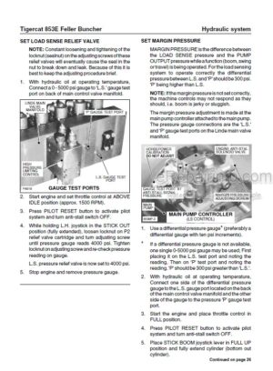
Case Drain Return Strainers
Filters
Hydraulic Circuit Diagram, Attachment Function
Hydraulic Circuit Diagram, Main Hydraulic System
Hydraulic Circuit Diagram, Pilot System
Hydraulic Fundamentals
Hydraulic Oil Tank
Hydraulic Schematic, Main Hydraulic Pump
Hydraulic System Overview
Set Load Sense Relief Valve Pressure
Set Margin Pressure
Test Main Hydraulic Pump Wear
-PILOT SYSTEM
Controls
Electrical Schematic, Pilot System
Hydraulic Circuit Diagram, Pilot System
Hydraulic Schematic
Pilot Supply Pressure Setting
Pilot System
Pilot System Components
Pilot System Electrical Circuits
-ELECTRICAL AND COMPUTERS
Cab Electrical Installation
Computer
Electrical Service And Diagnostic Kit
Electrical System Overview
Electrical System Schematic
Software
Upper Frame Electrical Installation
-ENGINE AND ANTI-STALL
Circuit Diagram, Anti-Stall
Circuit Diagram, Computer Control System
Circuit Diagram, Load Sensing
Electrical Schematic, Anti-Stall Circuit
Electrical Schematic, Load Sensing Circuit (Attachment Control Valve)
Electrical Schematic, Load Sensing Circuit (Attachment Pump)
Electrical Schematic, Load Sensing Circuit (Main Hydraulic Pump)
Engine Anti-Stall System
Engine Diagnostic Connector
Flex Drive Coupling
Hydraulic Schematic, Attachment Pump
Hydraulic Schematic, Main Hydraulic Pump
Hydraulic Schematic, Saw Pump
Load Sensing
Starting And Stopping The Engine
-COOLING SYSTEM
A/C Condensor And A/C System
Charge Air Cooler
Circuit Diagram, A/C Condenser And Refrigerant
Circuit Diagram, DEF Coolant Flow: Coolant Control Valve Closed
Circuit Diagram, DEF Coolant Flow: Coolant Control Valve Open
Coolant Pre-Heating System (Optional)
Cooling System
Diesel Exhaust Fluid (DEF) Coolant System
Electrical Schematic, Coolant Heater Unit
Electrical Schematic, Fan Control System
Fan Control System
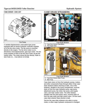
Fan Drive System
Fan System Testing
Hydraulic Oil Cooler Circuit
Hydraulic Schematic, Fan Drive Motor
Pressure Setting, Fan Pump
Radiator
Troubleshooting
Upper Frame Electrical Installation
-TRACK DRIVE
Hydraulic Circuit Diagram, Track Drive, Upper Structure Components
Hydraulic Circuit Diagram, Type B Track Drive, Undercarriage Components
Hydraulic Circuit Diagram, Type C Track Drive, Undercarriage Components
Hydraulic Drive Motor Control Valve Sections
Hydraulic Drive System
Hydraulic Schematic, Type B Track Drive
Hydraulic Schematic, Type C Track Drive
Important Track Drive Information
Measuring Track Sag
Parking Brake Disc Replacement
Pressure And Speed Settings Type B
Pressure And Speed Settings Type C
Rotary Manifold
Rotary Manifold Seal Installation
Summary Of Track Speed Adjustment Procedure (Types B And C)
Torquing Undercarriage Bolts
Track Drive Motor Case Drain Leakage
Track Drive Motor Description Type B
Track Drive Motor Drive Description Type C
Track Drive Motor Start-Up Procedure
Track Drive Motor Type Identification
Undercarriage Components
Wear Limits
-BOOM FUNCTIONS
Adjust Flow Cycle Times
ER Boom System Description
Hoist And Stick Functions (ER Boom System)
Hydraulic Circuit Diagram, Attachment Tilt Cylinder
Hydraulic Circuit Diagram, Conventional Boom System Hoist Cylinder
Hydraulic Circuit Diagram, Conventional Boom System Stick Cylinders
Hydraulic Circuit Diagram, ER Boom System Hoist And ER (Right Stick) Cylinders
Hydraulic Circuit Diagram, ER Boom System (Left) Stick Cylinder
Hydraulic Schematic, Attachment Tilt Cylinder
Hydraulic Schematic, Conventional Boom System Hoist And Stick Cylinders
Hydraulic Schematic, ER Boom System Hoist And Stick Cylinders (Left And Right)
Hydraulic Schematic, ER Boom Valve
Pressure Settings
Servicing The ER Boom System
Tilt Function
-LEVELING
Check Leveling Control Valve Port Relief Pressure
Check Leveling Speed
Hydraulic Circuit Diagram, Leveling System (Undercarriage Components)
Hydraulic Circuit Diagram, Leveling System (Upper Structure Components)
Hydraulic Schematic, Counterbalance Valve
Hydraulic Schematic, Leveling System
Leveling Circuit Description
Leveling Component Lubrication
Leveling Control Valve
Leveling Cylinder Counterbalance Valves
Leveling Cylinder Tapered Lock Pins
Leveling Electronic Adjustment
Side Pivot Axis Bearings
-SAW DRIVE
Hydraulic Circuit Diagram, Saw Drive
Hydraulic Schematic, Saw Control Valve
Hydraulic Schematic, Saw Drive
Hydraulic Schematic, Saw Pump
Maximum Displacement Setting, Saw Pump
Pressure Override Setting, Saw Pump
Saw Drive System
Standby Pressure Setting, Saw Pump
-ACCUMULATOR, CLAMPS, AND WRIST
Adjust Flow Cycle Times
Attachment Electronic Adjustment
Attachment Hydraulic System
Attachment Pump Pressure Setting
Attachment Valve Port Relief Valve Replacement
Attachment Valve Pressure Relief Valve Replacement
Hydraulic Circuit Diagram, Attachment Function
Hydraulic Schematic, Attachment Pump
Hydraulic Schematic, Clamp And Accumulator Attachment Valve
Hydraulic Schematic, Wrist Attachment Valve
Wrist Relief Valve Pressure Settings
-MISCELLANEOUS
Hydraulic Circuit Diagram, Power Roof
Hydraulic Schematic, Power Roof
Power Roof
Power Roof Pressure Settings
What you get
You will receive PDF file with high-quality manual on your email immediately after the payment.


Reviews
There are no reviews yet.