


Factory Service Manual For Toyota Reach Lift Truck. Manual Contains Illustrations, Instructions, Diagrams For Step By Step Remove And Install, Assembly And Disassembly, Service, Inspection, Repair, Troubleshooting, Tune-Ups.
Format: PDF
Language: English
Pages: 557
Number: 00700-CL220-01 (june 2004)
Bookmarks
Searchable
Wiring Diagrams
Hydraulic Diagrams
Model
Toyota Reach Lift Truck
7BRU18
7BRU23
7BDRU15
7BSU20
7BSU25
24 Volt Models – Serial No. 21,000 and Up
36 Volt Models – Serial No. 32,000 and Up
Contents
-HOW TO USE THIS MANUAL
Map Of The Manual
Manual Design
Start Page
-SAFETY
Definitions
General Safety
Battery Safety
Static Safety
Jacking Safety
Tie-Down For Transport
Welding Safety
-SYSTEMS OVERVIEW
Vehicle Specifications
General System Data
Modes of Operation
-SCHEDULED MAINTENANCE
Maintenance Guidelines
Daily or Every 8 Operating Hours
Monthly or Every 200 Operating Hours
Semi-annually or Every 1000 Operating Hours
Annually or Every 2000 Operating Hours
Lubricants
Lubrication and Inspection Points
-TROUBLESHOOTING
How to Use This Chapter
Electrical Troubleshooting Guidelines
Shorts to Frame Test
Hydraulic Troubleshooting Guidelines
Definitions
Electrical Connector Locator Chart
Electrical Connector Locator Photos
List of Troubleshooting Flowcharts
-ELECTRICAL CODES AND TESTS
Modes of Operation
Self-diagnosis Mode
Analyzer (ANL) Mode
Calibrate (Calibrate) Mode
Configure (Configure) Mode
Tuning (Tuning) Mode
Code Summary Table
Tests
Analog Tests (Category 1, Class 2)
-COMPONENT PROCEDURES
List of Component Procedures
Component Locator Photos
Frame and Accessories
Panels and Covers
Decals
Steering and Controls
Steering Wheel
Steer Tachometer
Steer Motor
Steer Controller
Control Handle
Traction and Braking
Deadman Pedal
Caster Assembly with Brake
Caster Assembly w/o Brake
Electromagnetic Brake
Electromagnetic Brake, Armature and Magnetic Coil
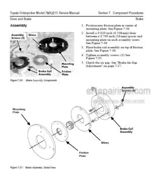
Brake Friction Plate
Drive Wheel
Drive Unit
Tooth Pattern of Drive Unit
Drive Housing Steering Bearing
Axle Seal Replacement
Electrical
Battery
Power Cables
Wiring Harness
Contactors, General
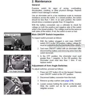
Switches (General)
Key Switch (S1)
EPO Switch (S2)
Lift Inhibit Switch (S4)
Mast Switch 1 (S6) (High Speed Travel Limit)
Deadman (Left Foot) Switch (S3)
Platform (Right Foot) Switch (S7)
Staging Switch (S8)
180° Sensor
Drive Wheel Position Proximity Sensors (360° Steering)
Steer Stop Proximity Sensors (180° Steering)
Drive Motor Speed/Direction Sensors
Horn
Motors, General
Electric Motor Tests
Drive Motor
Lift Motor
Traction Power Amplifier
Lift Power Amplifier
Fuses
Operator Display
Temperature Sensors (Lift And Traction Motor)
Brush Wear Sensors
Tractor Interface Card
Display Card
Light Assemblies
Fan Assemblies
Height Indicator (Optional)
Hydraulics
Hydraulic Fluid
Hydraulic Filter
Hydraulic Filter Adapter
Hydraulic Reservoir
Bleeding the Hydraulic System
Control Valve
Reach/Tilt/Sideshift Manifold
Solenoids
Lift Pump
Free Lift Cylinder Repair
Staging Cylinder Repair
Tilt Cylinder (3500 lb. Reach)
Tilt Cylinder (4500 lb. Reach)
Reach Cylinder
Lift/Auxiliary Pressure Relief
Velocity Fuses
Mast
Main Mast Assembly
Mast Roller Bearings
Lift Chains
Free Lift Chain Anchors
Staging Chain Anchors
Over the Mast Hose/Cable
Reach Carriage Assembly
Reach Carriage Hose Routing
Reach Carriage Wear Strip
Carriage Roller Bearings
Reach Carriage Lubrication Points
Fork Carriage Pivot Pins
Sideshift Carriage
Mast Guard
Carriage Bumpers
Forks
Load Wheels
Load Wheel Toe Plate Box
Load Backrest
-THEORY OF OPERATION
Electrical Functions
Braking System
Steering System
Traction System
Lift/Lower System
Auxiliary Hydraulic Functions
Indicators and Switches
-APPENDIX
Lubrication Equivalency Chart
Torque Chart – Standard (Ferrous)
Torque Chart – Standard (Brass)
Torque Chart – Metric
Decimal Equivalent Chart
Standard/Metric Conversions
Electrical Schematics
Electrical Schematic Legend
Hydraulic Schematic
INDEX
What you get
You will receive PDF file with high-quality manual on your email immediately after the payment.


Reviews
There are no reviews yet