


Factory Operators Manual For Zetor Tractor. Manual For Owners And Operators. It Contains Important Information And Instructions For Maintenance Description Of The Functions And Capabilities Of The System. Description Of Possible Faults / Problems And Their Solution.
Format: PDF
Language: English
Pages: 234
Number: 222.213.505 (february 2018)
Searchable
Model
Zetor Tractor
Crystal HD 150
Crystal HD 170
Contents
LOCATION OF SERIAL NUMBERS
-SAFETY INSTRUCTIONS FOR USERS
General Safety Regulations
Proper Clothing
Starting The Engine
Driving Operation
Risk Of The Tractor Overturning
Transportation Of Persons, Operation
Fire Prevention Principles
-PREVENTIVE DAILY MAINTENANCE
Driver’s Seat
Front Passenger’s Seat Notification
Protection Of Cab Against Aerosols
Level Of External And Internal Noise
The Level Of Vibrations On Driver’s Seat
Aggregation Tractor – Machine/Trailer
Tractors Equipped With Front End Loader
Principles For Operating Tractors Equipped With Front End Loader
Zetor Tractors Used For Work In The Woods
Safety Labels
Preventive Daily Maintenance
Preventive Daily Maintenance
Fuel System Leaks
Engine Oil Level
Cooling System
Windshield Washer Tank
Washer Nozzle
Fluid Reservoir For Front Axle Brake Control
Hydrostatic Steering
Air Cleaner
Cab Filtration
Hitches
Inspection Of Fouling Of Coolers
After Work With Front Implements And In Case Of Cooler Clogging
Tyres And Wheels
Short Functional Test
Tractor Operation Brakes
Trailer Brakes
-ACQUAINTANCE WITH THE TRACTOR
Safety Cabin
Opening The Door From The Outside
Opening The Door From The Inside
Rear Window
Side Window
Emergency Exits
Hinged Lid
Adjustable Screen And Cover Of The Swing Lid
Shelf
Rear View Mirrors
Internal Lighting
Cabin Steps Illumination
Aggregation Opening
Driver’s Seat
Passenger’s Seat
Tilting And Protrusion Of Steering Wheel
Control Panel On The Right Column Of The Cabin
Windscreen Wiper
Front Wiper Speed Switch
Rear Window Wiper
Windscreen Washer
Upper Working Lights Switching On
Control Panel On The Right Rear Mudguard
Switches Located On The Control Panel
Panel Of The Instrument Panel
Lights Switch
Lights Switch Between The Grill And The Cabin
Direction Lights, Lower Beam Head Lights, Head Lights And Hom Switches
Switch Box
Switch Box Key In The Position (0)
Switch Box Key In The Position (I)
Switch Box Key In The Position (II)
Manual Throttle
Pedals And Levers
Reversing Lever
Gear Shifting Lever
Gear Shifting Scheme
Road And Reduced Speeds Shifting Lever
PTO Revolutions Preselection Lever
Manual Brake Lever And Coupling For Semi-Trailer Control Lever
Battery Disconnector
Heating Control Panel, * Air-Condition
Heating Valve Control (A)
Switch Air-Condition (C)
Air Circulation In Cabin Control (D)
Proper Function Of The Heating And Air-Condition System
Fast Heating Of The Cabin Area
Fast Cooling Of The Space Of The Cabin
Immediately After Cooling The Cabin
Operation Of Heating Or Air-Condition With Tractor’s Work
Air-Condition And Heating Registers (A)
Front Windshield (B) Defrosting
Air Filter With Active Carbon
Fuel Tank
Fuel Tank Drain Plug
Minimum Fuel Amount In The Fuel Tank
Urea Tank
-INSTRUMENT PANEL
Instrument Panel – Signal Lamps
Instrument Panel – Instruments
Instrument Panel – Buttons
Display Description
Display – Change Of Display
Display – Display Of Air Pressure In The Air-Pressure System Of The Tractor
Display – Warning Of Low Air Pressure In The Air-Pressure System Of The Tractor
Display – Resetting Data
Display – Manual Brake
Display – Service Menu
Service Menu
Display – Indicator Of Service Inspection Intervals
Exceeding The Service Interval
Zeroing (Reset) Of The Indicator Of Service Inspection Intervals
Error Signalling
Display – Error Messages
Description Of The Display Of Error Messages
Symbols Of Tractor Nodes
Display – History Of Defects
Display – Setting Language Mutation
Display – Backlight Of Display
Display – Setting Of Day And Night Backlight Of The Display
Display – Setting The Automatic Mode Of The Display Backlight
Display – Setting And Calibration
Travel Speed Calibration
Setting Of Steering Sensors Of The Front Axle
Display – Machined Area
Machined Area Menu
Processed Area – User Selection
The Processed Area – Setting Of The Width Of Aggregation
Machined Area Record
System Of Treatment Of Exhaust Gases – Setting
Instrument Panel – Warning
Replenish Fuel
Add Urea
High Temperature Of The Cooling Liquid
Low Level Of The Cooling Liquid
High Temperature Of The Engine Oil
High Air Temperature In The Engine Air Intake System
Water In The Coarse Filter Of Fuel
High Oil Temperature In The Gearbox
Full Pushing Filter Of The Gearbox Distributor
Signalling Of Driver’s Seat
Indication Of Speed And Engine Power Reduction
Clutch Couplings Overheating Signalization
Signalization Of A Need To Replace Engine Oil Outside The Service Interval
Rear PTO Speed Lever Position Indication
-SYSTEM OF ADDITIONAL TREATMENT OF EXHAUST GASES
Conditions For DPF Operation
DPF Signalization
DPF Filter Regeneration
Conditions For SCR System Operation
Urea (Aqueous Urea Solution Aus 32, DEF)
Principles For Safe Handling Of Urea (Aus 32, DEF)
Error Signalling Of SCR System
Indication Of DPF And SCR Errors On The Display Of The Instrument Panel
Indication Of Amount Of Urea In The Tank
Reduction Of The Engine Power And Engine Revolutions
Long-Term Shutdown Of Tractor
Repairs And Maintenance Of The System Of Additional Treatment Of Exhaust Gases
-DRIVING OPERATION
Starting The Engine
Blocking Of The Start
Non-Permitted Starting
If You Do Not Succeed In Starting The Engine
Immediately After Start
Engine Heating
Error Signalling
Indication Of The Limitation Of The Engine Power And Engine Revolutions
Signalling Errors In The System Of Additional Treatment Of Exhaust Gases
Diesel Particle Filter
Filter Of Solid Particles – Indication Of Operation And Failures Of The System
Diesel Particle Filter Regeneration
Driver’s Seat – Safety Switch
Reversing Lever
Reversing Lever Position Signalization
Gear Shifting
Shifting Road And Reduced Speeds
Road And Reducing Speeds Lever Position Signalization
The Principles Of Appropriate Use Of Tractors
The Description Of The System Of Travel Clutches
The Way Of Controlling The Travel Clutch By
The Differences In Ways Of Controlling The Travel Clutch By
Interrupted Sound Signal
Dead Start Of The Tractor
Dead Start Of Tractor In Regular Operation – Automatic Dead Start Function
Dead Start By Means Of Automatic Dead Start Function
Dead Start Of Tractor In Regular Operation – Clutch Pedal
Dead Start – Using The Clutch Pedal
Change The Direction Of Drive
Change The Direction Of Drive By Means Of Reversing Lever
Change The Direction Of Drive – Using The Clutch Pedal
Gear Shifting
Gear Shifting – Using The Clutch Pedal
Gear Shifting – Using The Clutch Control Button On The Head Of Gear Shifting Lever
Blocking The Automatic Dead Start Function
Engine Speed Preselection System
Description Of The Engine Speed Preselection Functions
Driving The Tractor Using The Engine Speed Preselection System
Automatic Engine Speed Preset Mode
Automatic Engine Speed Preset Mode For Operation In Field Mode
Automatic Engine Speed Preset Mode For PTO Operation In Stationary Mode
Three-Gear Torque Multiplier
Signalization Of Multiplier Function
Increasing, Decreasing The Travel Speed By Two Gears
Multiplier Preselection Switch
Automatic Multiplier Shifting
Front Drive Axle Control
Driving With Engaged Front Axle Drive
Front Drive Axle Control – Manual Mode
Automatically Disconnect The Front Axle – Manual Mode
Front Drive Axle Control – Automatic Mode
Automatic Front Axle Control Mode
Suspension Front Drive Axle
Automatic Front Axle Suspension Mode
Front Axle Suspension Suspension Blocking Mode
Height Adjustment Of The Front Part Of The Tractor
Axle Lock Control Of Rear And Front Axle
Automatic Axle Lock Control Of Rear And Front Axle
Automatic Mode Of Differential Lock Control
Driving Up The Slope
Driving Down The Slope
Foot Brakes
Braking With One Brake Pedal
Turning On The One Pedal Braking System
Warning Signalization Of Air Pressured Drop
Emergency Braking
Unblocking The Tractor Brakes When The Air Pressure Drops
Hand Brake
Manual Brake – Signalization
Brakes Of Trailers And Semi-Trailers
Connection Of The Abs System Of The Trailer Or Semi-Trailer
Button To Temporarily Deactivate The Trailer Or Semi-Trailer Hydraulic Brakes
Temporary Deactivation Of The Trailer Or Semi-Trailer Air Brakes Using The Handbrake Lever
Air Brakes Of Trailers And Articulated Trailers
One-Hose And Two-Hose Brakes
One-Hose Brakes
Two-Hose Brakes
Hydraulic Brakes Of Trailers
Connecting And Disconnecting Quick Couplings Of Trailer Hydraulic Brakes
The Socket For Connection Of The Electrical Installation Of The Trailer Or Semi-Trailer
Stopping The Tractor – Manual Brake
Stopping The Engine
Leaving The Tractor
Warning Signalization Of Hydrostatic Steering Failure
Important Warnings
Limiting Travel Speed
-RUNNING IN THE TRACTOR
General Principles Of New Tractor Run-In In First 100 Hours Of Operation
In First 10 Hours Of Operation
From 100 Hours Of Operation
-TRANSPORTATION
Front Hook
Height Adjustment And Disassembly Of The CBM Stage Hitch
Automatic Mouth Of The CBM Stage Hitch
Swing Drawbar
Modular System Of Hitches For Trailers And Semi-Trailers
Swinging Draw-Bar Console Module
Swinging Draw-Bar Console With A Fixed Pin Module
Console With A 0 80 Ball Module
Hitch For A Single-Axle Cbm Semi-Trailer
Uncoupling Of A Single-Axle Trailer
Coupling Of A Single-Axle Trailer
Maximum Permissible Vertical Static Load Of Hitches For Trailers And Semi-Trailers
-DRIVE OF AGRICULTURAL MACHINERY
Work With PTO Shaft
Display Of Revolutions Of PTO Shafts
Replaceable End Points Of Rear PTO Shaft
Control Elements Of PTO Shafts
The Buttons For Activation Of PTO Shafts
Selection Switch Of Rear PTO Clutch Revolutions (PTO)
Rear PTO Shaft Revolutions Preselection Lever
Standard And Economical Independent Revolutions Of Rear PTO Shaft
Dependent And Independent Rear PTO Shaft Revolutions
Automatic Disengagement Of PTO Clutch
Setting Automatic Disengagement Of PTO Shaft Clutch – Display Description
Automatic Disengagement Of PTO Shaft Clutch – Return To Basic Setting
Work With Automatic Disengagement Of PTO Shaft Clutch
Facilitating Connection Of Joint Shaft Of An Aggregated Machine To The Tractor
Working Modes Of PTO Shafts
Activation Of The Rear PTO Shaft – Independent Revolutions – Common Working Mode
Activation Of The Rear PTO Shaft – Independent Revolutions – Stationary Working Mode
Deactivation Of The Rear PTO Shaft – Independent Revolutions
Rear PTO Shaft Switch – Dependent Speed – Ordinary Mode Of Operation
Front PTO Shaft
Activation Of The Front PTO Shaft – Common Working Mode
Activation Of The Front PTO Shaft – Stationary Working Mode
Deactivation Of The Front PTO Shaft
Maximum Transferred Output
Drive Of Machines With Greater Inertia Masses
-HYDRAULIC SYSTEM
Hydraulic System
Indication Of Low Oil Temperature
Hydraulic Pump
Control Elements Placement
Outer Hydraulic Circuit
Connecting And Disconnecting Quick-Couplers
Quick-Couplings With Drip Collection
Amount Of Oil Taken From Outer Hydraulic Drives
External Hydraulic Circuit Controls
Controls Of External Hydraulic Circuit Description
External Hydraulic Circuit Controls Activation
External Hydraulic Circuit Controls Function
Setting Oil Flow Through Quick Couplers
External Hydraulic Circuits Control By Means Of A Joystick
External Hydraulic Circuit Front Outlets And Front Three-Point Hitch
Front Outlets Of External Hydraulic Circuit – Standard Version Of The Tractor
Front Outlets Of External Hydraulic Circuit – Tractor With Auxiliary Switchboard For Front Hydraulic Circuit
Connecting Machines And Tools To External Hydraulic Circuit
-ELECTRO-HYDRAULIC SYSTEM
Control Element Functions
Equipment ‘off
Blocking Cancellation
Quick Sinking
Transport Of Implements
Stop Position
Vibration Compensator (Damper)
Limitation Of The Upper Position Of The Three-Point Hitch
Lowering Speed
Free Position
Setting The Control Of Three-Point Hitch
Manual Setting Of Control Of Three-Point Hitch
Automatic Control Of Three-Point Hitch
Using The Rear Control
External Control Buttons Of The Electro-Hydraulic System
Indication Of EHR-B Errors
Description Of Signals Of EHR-B Electro-Hydraulic System Errors
Description Of Minor Errors Of The EHR-B Electro-Hydraulic System
-HITCHES
Rear Three-Point Hitch
Safety Principles Of Working With The Three-Point Hitch
Height Adjustment Of The Lifting Draw-Bars
Fixed And Free Position Of The Lower Hydraulic Draw-Bars
Limiting Draw-Bars
Automatic Limiting Draw-Bars
Lower Draw Bar With CBM Hooks
Securing Lower Draw Bars With CBM Hooks
Upper Draw-Bar
Front Three-Point Hitch
Front Three-Point Hitch – Standard Version Of The Tractor
Controlling Front Three-Point Hitch Mode – Tractor Version With Auxiliary Switchboard For Front Hydraulic Circuits
Adjusting The Lowering Rate Of The Front Three-Point Hitch
Hydraulic Lock Of The Front Three-Point Hitch
Working And Transport Position Of The Front Three-Point Hitch
Driving With Agricultural Machines Attached To The Front Three-Point Hitch
-WHEEL TRACK CHANG
Front Wheels Track Of Front Drive Axle In Tractors Equipped With Non-Removable Discs
Toe-In Of The Wheels Of The Front Driving Axle
Adjustment Of Toe-In Of The Wheels Of The Front Driving Axle
Front Drive Axle Fenders
Setting Wheel Stops With Front Drive Axle
The Gauges Of The Tractor Rear Wheels Equipped With Solid Discs
-BALLAST WEIGHTS
Rear Wheel Weights
Front Weights
Weight Of The Front Three-Point Hitch
Valve For Filling Tyre Tubes With Liquid
Procedure Of Filling The Tyres With Liquid
Procedure Of Draining Liquid From The Tyres
Wedging The Front Wheels
Antifreeze Solution For Tyre Filling
-ELECTRIC INSTALLATION
Basic Service Information
Accumulator Battery
Battery Disconnector
Accumulator Battery Maintenance
Alternator
Alternator Maintenance
Electric Installation Overload
Fuse Panels
Checking The Adjustment Of The Front Grill Headlights
Adjusting The Front Grill Headlights
List Of Lamps
-TRACTOR MAINTENANCE
Service Inspections
Steps Performed Daily Before The Start Of Work
Steps Performed Every 50 Hours Of Work
Steps Performed Every 100 Hours Of Work
Steps Performed Every 500 Hours Of Work
Steps Performed Outside The Interval Of 500 Hours Of Work
Monthly Performed Actions
Filling And Filter Replacement
Used Operation Liquids And Filling – Quantities
Zetor Service Fillings
Oil In The Gearbox And Final Drivehousing
Oil For The Front Driving Axle
Motor Oils
Specification Of The Oil For The Gearbox Housing And The Final Drive Housing
Specification Of Oil For The Front Driving Axle
Other Recommended Service Fillings Tested On Zetor Tractors
Oil To Gear Systems Of Tractors
Front PTO Oil
Oil For The Front Driving Axle
Hydraulic Brake Liquid For The Tractors
Plastic Lubricant For The Tractor
A/C Coolant
Liquid For The Cooling System Of The Tractors
Fuel
Urea (Urea Solution Aus 32)
Tractor Greasing Scheme
Safety Instructions For Lubrication Of The Tractor
Bearing Housing Of The Front Axle Drive Shaft
Suspension Front Drive Axle
Hitch For A Single-Axle Semi-Trailer
Front Three-Point Hitch
Three-Point Hitch
Hitch Mouth For A Trailer
Technical Maintenance Of The Tractors After A General Overhaul Of The Main Groups
-MAINTENANCE INSTRUCTIONS
Opening The Hood
Checking The Oil Level In The Engine
Draining Oil From The Engine
Filling The Engine With Oil
Replacing Full-Continuous Motor Oil Filter
Fuel Filtering
Raw Fuel Filter Clearing
Cartridge Replacement In The Raw Fuel Filter
Cartridge Replacement In The Fine Fuel Filter
Fuel System Venting
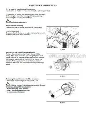
Dry Air Cleaner Maintenance Instructions
Air Cleaner Disassembly
Recovery Of The Main Air Cleaner Element
Replacing The Safety Element Of The Air Cleaner
Reassembly Of The Air Cleaner Elements
Bleeding The Hydraulic Circuit Of The Hydrostatic Steering
Replacing The Hydrostatic Steering Hoses
Replacing Coolant
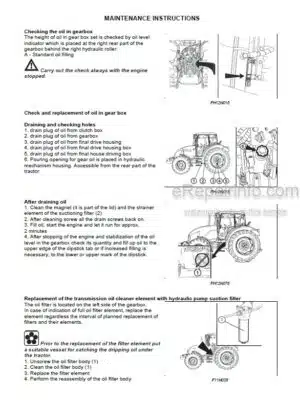
Check And Replacement Of Oil In Gear Box
Draining And Checking Holes
Checking The Oil In Gearbox
After Draining Oil
Replacement Of The Transmission Oil Cleaner Element With Hydraulic Pump Suction Filter
Insertion Piece Replacement Of The Oil Cleaner With Delivery Filter Of The Gearbox Switchboard
Cleaner Insert In The Tractor’S Brake Air Control Valve Replacement
Replacement Of Filter Element Of Urea Filter
Filling, Controlling And Draining Hole Of Oil Of Front Drive Axle
Filling, Controlling And Draining Hole Of Oil Of Front Wheels Reducers
Front PTO
Carbon Filter Installation Instructions
Cleaning The Heating Filters
Air Filter With Active Carbon
Air-Conditioning Maintenance
Checking The Air Systems For Leaks
Maintenance And Treatment Of Tyres
Tractor Shutdown And Recommended Points For Tractor Lifting
-ADJUSTMENT
Adjusting Valve Clearance
Flat Belt Drive Tension Of Accessories
Bleeding The Front Drive Axle Brake System
Brake Pedal Free Play Setting
Brake Adjustment
Adjustment Of The Lifting Draw-Bars Of The Hitch For A Single-Axle Semi-Trailer
Adjusting The Bowden Cable
-MAIN TECHNICAL PARAMETERS
Main Tractor’S Parameters (Mm)
Technical Data Of Engines
Permitted Maximum Load Of Front Axle (Kg)
Permitted Maximum Load Of Rear Axle (Kg)
Permitted Maximum Weight Of Set ‘tractor + Mounted Machine’ (Kg)
Manoeuvrability Condition
Front Tires Steerability
Change Of The Load-Bearing Capacity Of The Front Tyres (%)
Bearing Capacity Of Rear Tires
Change Of The Load Capacity Of The Rear Tyres (%)
Permitted Combinations Of Wheels For Tractors
Performance On Rear PTO Shaft
Lifting Force Of The Three-Point Hitch
Tensile Force
Speed Of Tractor With Engine Revolutions Of 2 100 Rpm And Parameter Of Rear Wheels (Km/H)
Dependent PTO Shaft Revolutions With Nominal Engine Revolutions
Independent Rear PTO Shaft Revolutions
Speed Of The Zuidberg Front PTO
Clearance-Circle And Turning Circle Diameter
Calculation Of Tractor Load Limit
INDEX
What you get
You will receive PDF file with high-quality manual on your email immediately after the payment.


Reviews
There are no reviews yet.