


Factory Service Technical Manual and Workshop Manual For Hitachi EX75UR-5, 75US-5 Excavators. Tons of illustrations, instructions, diagrams for step by step remove and install, assembly and disassembly, service, inspection, repair, troubleshooting, tune-ups.
Format: PDF
Language: English
Bookmarks: Yes
Searchable: Yes
Wiring Diagrams: Yes
Hydraulic Diagrams: Yes
Model
Hitachi EX75UR-5, 75US-5
Contents
1.Technical Manual
INTRODUCTION
SAFETY
-GENERAL
–SPECIFICATIONS
Specifications
Working Ranges and Machine Transportation Dimensions
Component Specification
–COMPONENT LAYOUT
Main Components
Electrical System (Overall System)
Electrical System (Monitor and Switches)
Others
-SYSTEM
–CONTROL SYSTEM
Outline
Engine Control
Pump Control
Other Controls
–FRONT CONTROL SYSTEM
Outline
Front Function Control
–HYDRAULIC SYSTEM
Outline
Main Circuit
Pilot Circuit
–ELECTRICAL SYSTEM
Outline
Power Source Circuit (Key Switch:OFF)
Bulb Check Circuit (Key Switch:ON)
Preheat Circuit (Key Switch:Heat)
Engine Start Circuit (Key Switch:Start)
Charging Circuit (Key Switch:ON)
Surge Voltage Prevention Circuit
Accessory Circuit
Engine Stop Circuit
-COMPONENT OPERATION
–PUMP DEVICE
Outline
Main Pumps (1 and 2)
Main Pump 3 and Pilot Pump
–SWING DEVICE
Outline
Swing Motor
Valve Unit
Swing Reduction Gear
–CONTROL VALVE
Outline
Hydraulic Circuit
Flow Combiner Valve
Main Relief Set Pressure Change
Boom Anti-Drift Valve
Main Relief Valve
Overload Relief Valve
–PILOT VALVE
Outline
Operation
–TRAVEL DEVICE
Outline
Travel Motor
Parking Brake
Travel Brake Valve
Travel Reduction Gear
–OTHERS (UPPERSTRUCTURE)
Pilot Shut-Off Valve
Shockless Valve
9-Unit Solenoid Valve (EX75UR-5)
Solenoid Valve Unit
Offset Anti-Drift Valve (EX75UR-5)
EC Motor
–OTHERS (UNDERCARRIAGE)
Swing Bearing
Center Joint
Track Adjuster
-OPERATIONAL PERFORMANCE TEST
–INTRODUCTION
Operational Performance Tests
Preparation for Performance Test
–STANDARD
Operational Performance
Standard Table
Main Pump P-Q Diagram
Sensor Activating Range
–ENGINE TEST
Engine Speed
Engine Compression Pressure
Valve Clearance
Nozzle Check
Injection Timing
–EXCAVATOR TEST
Travel Speed
Track Revolution Speed
Mistrack Check
Travel Motor Leakage
Swing Speed
Swing Function Drift Check
Swing Motor Leakage
Maximum Swingable Slant Angle
Swing Bearing Play
Hydraulic Cylinder Cycle Time
Dig Function Drift Check
Control Lever Operating Force
Control Lever Stroke
Boom Raise/Swing Combined Operation Check
–COMPONENT TEST
Primary Pilot Pressure
Secondary Pilot Pressure
Main Relief Valve Set Pressure
Overload Relief Valve Set Pressure
Main Pump Flow Rate Measurement
Swing Motor Drainage
Travel Motor Drainage
–ADJUSTMENT
Engine Speed Adjustment and
Engine Learning
Boom Lowering Method when Engine Stalling
Check of Governor Lever and Fuel Cut Lever Position
Assembly and Adjustment of Link for Arm Angle Sensor (EX75UR-5)
Initial Setting of the Angle Sensor
Initializing the Depth Limit Control System (EX75UR-5)
-TROUBLESHOOTING
–GENERAL
Introduction
Diagnostic Procedures
DrEX Operation
Main Controller Fault Code List
Auto-Marccino Control Unit Fault Code List
Main Controller Monitoring Function
Auto-Marccino Control Unit Monitoring Function (EX75UR-5)
DrEX Special Function (Service Mode) (EX75UR-5)
–COMPONENT LAYOUT
Main Components
Electrical System (Overview)
Electrical System (Monitor and Switches)
Component in Control Valve
–TROUBLESHOOTING A
Troubleshooting A Procedure
Fault Code 01 (Abnormal EC Sensor)
Fault Code 07 (Abnormal Engine Control Dial Angle)
–TROUBLESHOOTING B
Troubleshooting B Procedure
Relationship between Machine Trouble Symptoms and Suspected Parts
Correlation between Trouble
Symptoms and Part Failures
Engine System Troubleshooting
All Actuator Control System Troubleshooting
Front Attachment Control System Troubleshooting
Swing System Troubleshooting
Travel System Troubleshooting
Blade System Troubleshooting
–TROUBLESHOOTING C
Troubleshooting C (Troubleshooting for Monitor) Procedure Malfunction of Coolant Temperature Gauge
Malfunction of Fuel Gauge
Malfunction of Indicator Light Check System
Malfunction of Alternator Indicator
Malfunction of Engine Oil Pressure Indicator
Malfunction of Overheat Indicator
Malfunction of Fuel Level Indicator
Malfunction of Air Filter Restriction Indicator
Malfunction of Buzzer
Malfunction of Hour Meter
–TROUBLESHOOTING D (EX75UR-5)
Troubleshooting D Procedure
Auto-Marccino Control Unit System Fault Code List
Fault Code 03
Fault Code 05, 06
Fault Code 07, 08
Fault Code 09
Fault Code 11, 12, 13
Fault Code 14, 15, 16, 19
Fault Code 24
Fault Code 40, 41
Fault Code 43, 45,47
Fault Code 50, 51,52
Fault Code 60, 61,62
Fault Code 80, 81,82, 83
Fault Code 90
Fault Code 91
–ELECTRICAL SYSTEM INSPECTION
Precautions for Inspection and Maintenance
Instructions for Disconnecting Connectors
Fuse Continuity Test
Fusible Link Inspection
Battery Voltage Check
How to Troubleshooting Alternator Malfunctions Alternator Check
Continuity Check
Voltage and Current Check
Check by False Signal
Test Harness
2.Workshop Manual
INTRODUCTION
SAFETY
-GENERAL INFORMATION
–PRECAUTIONS FOR DISASSEMBLING AND ASSEMBLING
Precautions for Disassembling and Assembling
–TIGHTENING
Tightening Torque Specification
Torque Chart
Piping Joint
Periodic Replacement of Parts
-UPPERSTRUCTURE
–CAB
Remove and Install Cab
Dimensions of Cab Glass
–COUNTERWEIGHT
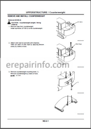
Remove and Install Counterweight
–MAIN FRAME
Remove and Install Main Frame
–PUMP DEVICE
Remove and Install Pump Device
Disassemble Pump Device
Assemble Pump Device
Maintenance Standard
Disassemble and Assemble Pilot Pump
–CONTROL VALVE
Remove and Install Control Valve 1
Disassemble Control Valve 1
Assemble Control Valve 1
Remove and Install Control Valve 2
Disassemble Control Valve 2
Assemble Control Valve 2
–SWING DEVICE
Remove and Install Swing Device
Disassemble Swing Device
Assemble Swing Device
Disassemble Swing Motor
Assemble Swing Motor
Maintenance Standard
–PILOT VALVE
Remove and Install Right Pilot Valve
Remove and Install Left Pilot Valve
Disassemble Right and Left Pilot Valves
Assemble Right and Left Pilot Valves
Remove and Install Travel Pilot Valve
Disassemble Travel Pilot Valve
Assemble Travel Pilot Valve
Remove and Install Offset Pilot Valve
Disassemble Offset Pilot Valve
Assemble Offset Pilot Valve
–PILOT SHUT-OFF VALVE
Remove and Install Pilot Shut-Off Valve
Disassemble Pilot Shut-Off Valve
Assemble Pilot Shut-Off Valve
–SHOCKLESS VALVE
Remove and Install Shockless Valve
Disassemble and Assemble Shockless Valve
–SOLENOID VALVE
Remove and Install 9-Spool Solenoid Valve Unit
Disassemble and Assemble 9-Spool Solenoid Valve Unit
Disassemble Proportional Solenoid Valve
Assemble Proportional Solenoid Valve
Disassemble and Assemble ON-OFF Solenoid Valve
Remove and Install Solenoid Valve Unit
Disassemble and Assemble Relief Valve
Disassemble and Assemble Unload Valve
–HOLDING VALVE
Remove and Install Holding Valve
Disassemble Holding Valve
Assemble Holding Valve
-UNDERCARRIAGE
–SWING BEARING
Remove and Install Swing Bearing
Disassemble Swing Bearing
Assemble Swing Bearing
–TRAVEL DEVICE
Remove and Install Travel Device
Disassemble Travel Device
Assemble Travel Device
Disassemble Travel Motor
Assemble Travel Motor
Disassemble and Assemble Brake Valve
Maintenance Standard
–CENTER JOINT
Remove and Install Center Joint
Disassemble Center Joint
Assemble Center Joint
Maintenance Standard
–TRACK ADJUSTER
Remove and Install Track Adjuster
Disassemble Track Adjuster
Assemble Track Adjuster
–UPPER AND LOWER ROLLER
Remove and Install Upper Roller
Disassemble and Assemble Upper Roller
Remove and Install Lower Roller
Disassemble Lower Roller
Assemble Lower Roller
Maintenance Standard
–TRACK
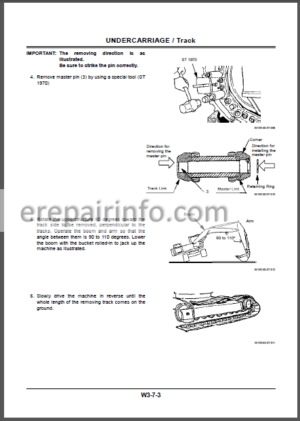
Remove and Install Track
Maintenance Standard
-FRONT ATTACHMENT
–FRONT ATTACHMENT
Remove and Install Front Attachment
Maintenance Standard
–CYLINDER
Remove and Install Cylinder
Disassemble Cylinder
Assemble Cylinder
Maintenance Standard
-ENGINE AND ACCESSORY
–GENERAL INFORMATION
General Repair Instructions
Notes on the Format of
This Manual
Main Data and Specifications
Tightening Torque Specifications
–MAINTENANCE
Model Identification
Injiction Pump Identification
Lubricating System
Fuel System
Cooling System
Valve Clearance Adjustment
Injection Timing
Compression Pressure
Measurement
Recommended Lubricants
Engine Repair Kit
–ENGINE ASSEMBLY 1 (DISASSEMBLY)
General Description
Disassembly
–ENGINE ASSEMBLY 2 (INSPECTION AND REPAIR)
Inspection and Repair
–ENGINE ASSEMBLY 3 (REASSEMBLY)
Reassembly
–LUBRICATING SYSTEM
Main Data and Specification
General Description
Oil Pump
Oil Filter with Built-in Oil Cooler
–COOLING SYSTEM
Main Data and Specification
General Description
Thermostat
–FUEL SYSTEM
Main Data and Specification
General Description
Injection Nozzle
Injection Pump Calibration Data
–ENGINE ELECTRICALS
Starter
Alternator
–TROUBLESHOOTING
Hard Starting
Unstable Idling
Insufficient Power
Excessive Fuel Consumption
Excessive Oil Consumption
Overheating
Whity Exhaust Smoke
Darkish Exhaust Smoke
Oil Pressure does not Rise
Abnormal Engine Noise
–SPECIAL TOOL LIST
Special Tool List
–REPAIR STANDARDS
General Ruler
Repair Standard Chart
–CONVERSION TABLE
Length
Area
Volume
Mass
Pressure
Torque
Temperature
What you get
You will receive PDF file with high-quality manual on your email immediately after the payment.


Reviews
There are no reviews yet.