


Factory Technical Manual and Workshop Manual For Hitachi EX60-5 75UR-3 75URLC Excavators. Tons of illustrations, instructions, diagrams for step by step remove and install, assembly and disassembly, service, inspection, repair, troubleshooting, tune-ups.
Format: PDF
Language: English
Bookmarks: Yes
Searchable: Yes
Wiring Diagrams: Yes
Hydraulic Diagrams: Yes
Model
Hitachi EX60-5, EX75UR-3, 75URLC-3
Contents
1.Technical Manual
-GENERAL
–SPECIFICATION
Specifications
Working Ranges and Machine Transportation Dimensions
–COMPONENT LAYOUT
Main Components
Electrical System (Overall System)
Electrical System (Monitor and Switches)
Pump Device
Swing Device
Travel Device
–COMPONENT SPECIFICATION
Engine
Engine Accessories
Hydraulic Component
Electrical Equipment
-SYSTEM
–CONTROL SYSTEM
Outline
Engine Control
Pump Control
Precise Swing Mode Control (EX75UR-3 and EX75URLC-3)
–FRONT CONTROL SYSTEM
Outline
Front Function Control
Front Function Limit Control
Group 3 Hydraulic System
Outline
Pilot Circuit
Main Circuit
–ELECTRICAL SYSTEM
Outline
Power Circuit (Key Switch:OFF)
Bulb Check Circuit
Preheat Circuit
Starting Circuit (Key Switch:Start)
Charging Circuit (Key Switch:ON)
Surge Voltage
Prevention Circuit
Accessory Circuit
Engine Stop Circuit
-COMPONENT OPERATION
–PUMP DEVICE
Outline
Main Pumpl
Main Pump 2 and Pilot Pump
–SWING DEVICE
Outline
Swing Motor
Parking Brake Switch Valve
Valve Unit
Swing Reduction Gear
–CONTROL VALVE
Outline
Control Valve Layout
Hydraulic Circuit
Flow Combiner Valve
Main Relief Set Pressure Change
Boom Anti-Drift Valve (EX60-5)
Main Relief Valve
Overload Relief Valve
–PILOT VALVE
Outline
Operation
–TRAVEL DEVICE
Outline
Travel Motor
Parking Brake
Travel Brake Valve
Travel Reduction Gear
–OTHERS (UPPERSTRUCTURE)
Pilot Shut-Off Valve
Swing Mode Control Valve
Shockless Valve
7-Spool Solenoid Valve Unit (EX75US-3)
Pilot Relief Valve
EC Motor
–OTHERS (UNDERCARRIAGE)
Swing Bearing
Center Joint
Track Adjuster
-OPERATIONAL PERFORMANCE TEST
–INTRODUCTION
Operational Performance Tests
Preparation For Performance
Test
–STANDARD
Operational Performance Standard Table
Main Pump P-Q Diagram
Sensor Activating Range
–ENGINE TEST
Engine Speed
Engine Compression Pressure
Valve Clearance
Nozzle Check
Injection Timing
–EXCAVATOR TEST
Travel Speed
Track Revolution Speed
Mistrack Check
Travel Motor Leakage
Swing Speed
Swing Function Drift Check
Swing Motor Leakage
Maximum Swingable Slant Angle
Swing Bearing Play
Hydraulic Cylinder Cycle Time
Dig Function Drift Check
Control Lever Operating Force
Control Lever Stroke
Boom Raise/Swing Combined Operation Check
Bucket/Cab Collision Prevention System Check (EX75UR-3)
–COMPONENT TEST
Primary Pilot Pressure
Secondary Pilot Pressure
Main Relief Valve Set Pressure
Overload Relief Valve Set Pressure
Main Pump Flow Rate Measurement
Swing Motor Drainage
Travel Motor Drainage
–ADJUSTMENT
Engine Speed Adjustment and Engine Learning
Boom Lowering Method when Engine Stalling
Check of Governor Lever and Fuel Cut Lever Position
-TROUBLESHOOTING
–GENERAL
Introduction
Diagnostic Procedures
DrEX Operation
Main Controller Fault Code List
Auto-MARCCINO Control Unit Fault Code List (EX75UR-3)
Main Controller Monitoring Function
Auto-MARCCINO Control Unit Monitoring Function (EX75UR-3)
DrEX Special Function (Service Mode) (EX75UR-3)
–COMPONENT LAYOUT
Main Components
Electrical System (Overview)
Electrical System (Monitor and Switches)
Pump Device
Swing Device
Travel Device
Component in Control Valve
–TROUBLESHOOTING A
Troubleshooting A Procedure
Fault Code 01 (Abnormal EC Sensor)
Fault Code 07 (Abnormal Engine Control Dial Angle)
–TROUBLESHOOTING B
Troubleshooting B Procedure
Relationship between Machine Trouble Symptoms and Suspected Parts
Correlation between Trouble Symptoms and Part Failures
Engine System Troubleshooting
All Actuator Control System Troubleshooting
Front Attachment Control System Troubleshooting
Swing System Troubleshooting
Travel System Troubleshooting
Blade System Troubleshooting
–TROUBLESHOOTING C
Troubleshooting C Procedure (Troubleshooting for Monitor)
Malfunction of Coolant Temperature Gauge
Malfunction of Fuel Gauge
Malfunction of Indicator Light Check System
Malfunction of Alternator Indicator
Malfunction of Engine Oil Pressure Indicator
Malfunction of Overheat Indicator
Malfunction of Fuel Level Indicator (EX75UR-3, EX75URLC-3)
Malfunction of Air Filter Restriction Indicator
Malfunction of Electrolyte Level lndicator(EX75UR-3 EX75URLC-3)
Malfunction of Buzzer
Malfunction of Hour Meter
–TROUBLESHOOTING D
Troubleshooting D Procedure (EX75UR-3)
Auto-Marccino Control Unit
System Fault Code List
Fault Code 03
Fault Code 07
Fault Code 08
Fault Code 11, 12 13
Fault Code 14 15 16 20
Fault Code 40 41 42,44
Fault Code 43 45 47
Fault Code 50 51 52
Fault Code 60 61 62
Fault Code 80 81 82
Fault Code 90
–ELECTRICAL SYSTEM INSPECTION
Precautions for Inspection andB Maintenance
Instructions for Disconnecting Connectors
Fuse Continuity Test
Fusible Link Inspection
Bзпeгу Voltage Check
How to Troubleshoot Alternator Malfunctions
Continuity Check
Voltage and Current Check
Check by False Signal
Test Hamess
2.Workshop Manual
SAFETY
-GENERAL INFORMATION
–PRECAUTIONS FOR DISASSEMBLING AND ASSEMBLING
Precautions for Disassembling and Assembling
Maintenance Standard Terminology
–TIGHTENING TORQUE
Tightening Torque Specification
Torque Chart
Piping Joint
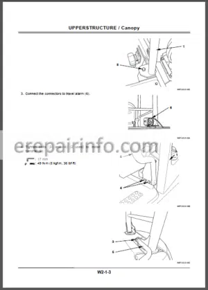
-UPPERSTRUCTURE
–CAB
Remove and Install Cab
Dimensions of the Cab Glass
–COUNTERWEIGHT
Remove and Install Counterweight
–MAIN FRAME
Remove and Install Main Frame
–PUMP DEVICE
Remove and Install Pump Device
Disassemble Main Pump
Assemble Main Pump
Disassemble and Assemble Pilot Pump
Disassemble and Assemble Gear Pump
Maintenance Standard
–CONTROL VALVE
Remove and Install Control Valve
Disassemble Control Valve
Assemble Control Valve
Disassemble Blade Control Valve
Assemble Blade Control Valve
–SWING DEVICE
Remove and Install
Swing Device
Disassemble Swing Reduction Gear
Assemble Swing Reduction Gear
Disassemble Swing Motor
Assemble Swing Motor
Maintenance Standard
–PILOT VALVE
Remove and Install Pilot Valve
Disassemble Pilot Valve for Front Attachment
Assemble Pilot Valve for Front Attachment
Disassemble Offset Pilot Valve
Assemble Offset Pilot Valve
–PILOT SHUT-OFF VALVE
Remove and Install Pilot Shut-off Valve
Disassemble Pilot Shut-off Valve
Assemble Pilot Shut-off Valve
–SHOCKLESS VALVE
Remove and Install Shockless Valve
Disassemble and Assemble Swing Shockless Valve
Disassemble and Assemble Front Attachment Shockless Valve
–SOLENOID VALVE
Remove and Install Solenoid Valve Unit
Disassemble and Assemble 7-Spool Solenoid Valve Unit
Disassemble Proportional Solenoid Valve
Assemble Proportional Solenoid Valve
–PILOT RELIEF VALVE UNIT
Remove and Install Pilot Relief Valve Unit
Disassemble Pilot Relief Valve Unit
Assemble Pilot Relief Valve Unit
–SWING MODE CONTROL VALVE
Remove and Install Swing Mode Control Valve
Disassemble and Assemble Swing Mode Control Valve
-UNDERCARRIAGE
–SWING BEARING
Remove And Install Swing Bearing
Disassemble Swing Bearing
Assemble Swing Bearing
–TRAVEL DEVICE
Remove And Install Travel Device
Disassemble Travel Device
Assemble Travel Device
Disassemble Travel Motor
Assemble Travel Motor
Disassemble And Assemble Brake Valve
Maintenance Standard
–CENTER JOINT
Remove And Install Center Joint
Disassemble Center Joint
Assemble Center Joint
–TRACK ADJUSTER
Remove And Install Track Adjuster
Disassemble Track Adjuster
Assemble Track Adjuster
–FRONT IDLER
Remove And Install Front Idler
Disassemble Front Idler
Assemble Front Idler
Maintenance Standard
–UPPER ROLLER AND LOWER ROLLER
Remove and Install Upper Roller
Remove and Install Lower Roller
Disassemble and Assemble Lower Roller
Maintenance Standard
–TRACK LINK
Remove and Install Track
Maintenance Standard
Remove and Install Rubber Track
Maintenance Standard
–FRONT ATTACHMENT
–FRONT ATTACHMENT
Remove and Install
Front Attachment
Maintenance Standard
Standard Dimensions for Arm and Bucket Connection
–CYLINDER
Remove and Install Cylinder
Disassemble Cylinder
Assemble Cylinder
Maintenance Standard
-ENGINE AND ACCESSORY
–GENERAL
Engine Specification
Identification
Lubrication
–INSPECTION AND MAINTENANCE
Engine Main Body
Lubricating System
Cooling System
Fuel System
Intake And Exhaust System
Electrical System
–ENGINE SERVICING
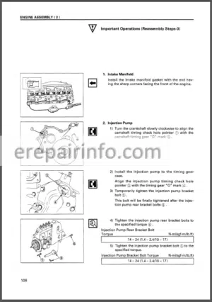
Manifold
Rocker Cover
Rocker Shaft
Cylinder Head
Gear Train
Injection Pump
Oil Pan
Oil Cooler
Oil Pump
Water Pump
Thermostat
–ENGINE MAIN BODY OVERHAULING
Precaution for Overhauling
Engine Main Body Overhauling
–SERVICE DATA
Engine Major Component Tightening Torque
Engine Main Body Specifications
Standard Tightening Torque
–TROUBLESHOOTING
Trouble Shooting Chart
Hou to Use the Chart
What you get
You will receive PDF file with high-quality manual on your email immediately after the payment.


Reviews
There are no reviews yet.