


Factory Service Manual For Bomag Single Drum Roller. Manual Contains Illustrations, Instructions, Diagrams For Step By Step Remove And Install, Assembly And Disassembly, Service, Inspection, Repair, Troubleshooting, Tune-Ups.
Format: PDF
Language: ENG
Pages: 1332
Number: 00891163 (november 2010)
Bookmarks: Yes
Searchable: Yes
Wiring Diagrams: Yes
Hydraulic Diagrams: Yes
Model
Bomag Single Drum Roller
BW211D-40
BW211PD-40
BW212D-40
BW212PD-40
BW213D-40
BW213PD-40
S/N 101 582 42 . . . .
S/N 101 582 43 . . . .
S/N 101 582 44 . . . .
S/N 101 582 47 . . . .
S/N 101 582 48 . . . .
S/N 101 582 49 . . . .
S/N 101 582 55 . . . .
S/N 861 583 00 . . . .
S/N 101 583 02 . . . .
S/N 101 583 03 . . . .
S/N 101 583 48 . . . .
S/N 101 583 49 . . . .
S/N 101 583 50 . . . .
S/N 861 583 01 . . . .
S/N 210 583 04 . . . .
Contents
-GENERAL
Introduction
Safety Regulations
General Repair Instructions
Tightening Torques
-TECHNICAL DATA
Technical Data
-MAINTENANCE
General Notes On Maintenance
Fuels And Lubricants
Table Of Fuels And Lubricants
Running-In Instructions
Maintenance Chart
-CONNECTION OVERVIEW
Connection Overview
-TESTS AND ADJUSTMENTS
Special Tools, Tests And Adjustments
Checking The Rotation Speeds
Checking / Adjusting The Neutral Positions Of The Travel Pump
Pressure Tests In The Travel Circuit
Checking / Adjusting The Vibrator Shaft Speeds
Pressure Measurements In The Vibration Circuit
Check The Leakage Rate Of The Vibration Motor
Pressure Test In Steering Circuit
-FLUSHING AND BLEEDING
Special Tools For Flushing
Flushing – General
Flushing Schematic Travel Circuit (Distribution Travel Pump)
Flushing The Travel Circuit (Travel Pump Distribution)
Flushing Schematic Travel Circuit (Distribution Axle Motor)
Flushing The Travel Circuit (Axle Motor Distribution)
Flushing Schematic For Vibration Drive
Flushing The Vibration Circuit
Bleeding The Travel Circuit
Bleeding The Vibration Circuit
-CADDY WIRING DIAGRAMS
Understanding Circuit Diagrams
Circuit Symbols In The Circuit Diagram
Identification Of Switch Blocks In The Caddy Wiring Diagram
-E-PLAN WIRING DIAGRAMS
Understanding Wiring Diagrams
Circuit Symbols In The Circuit Diagram
Identification Of Switch Blocks In The Wiring Diagram
-ELECTRICS
Designation Of Components In The Wiring Diagram
Terminal Designations In Wiring Diagram
Battery Ground And Analog Ground
Current And Voltage
Resistance
Series / Parallel Connection
Ohm’s Law
Electrical Energy
Formula Diagram
Metrology
Diodes, Relays, Fuses
Telemecanique Switch
Plug Connectors
Magnetic Coil Plug
Deutsch Plug, Series DT And DTM
Plugs And Terminals In Spring Clamping Technology
Inductive Proximity Switches
Angle Sensors
Acceleration Transducer
Batteries
Battery Maintenance
Main Battery Fuse
Starting With Jump Wires
Generator
Replacing The Voltage Regulator
Electric Starter
Operators Stand, Old Design
Operators Stand, New Design
Cabin
Fuses, Old Design
Fuses, New Design
Electronic Control Units
Checking The Voltage Supply For The Control Unit
Diagnostics Concept
-582 502 15 DUST PROTECTION / 582 502 16 GASKET
Assembling The Dust Protection
-ELECTRONIC MODULES
BEM, Bomag Evib-Meter
Electrics Module A68
Electric Module K04
Electric Module A72
Electric Module A108
-SPEEDOMETER MODULE
Speedometer Module
-SERVICE TRAINING
Service Training
-ENGINE
Diesel Engine, General
Service Side
Starter Side
Lubrication Oil Circuit
Oil Pressure Switch And Low Oil Pressure Circuitry
Check The Engine Oil Level
Changing Engine Oil And Oil Filter Cartridges
Coolant Circuit
Coolant Temperature Switch
Disassembling And Assembling The Coolant Temperature Switch
Replacing The Thermostat
Checking The Thermostat In Disassembled State
Check The Coolant Level
Change The Coolant
Checking The Anti-Freeze Concentration
Clean The Cooling Fins On Engine And Hydraulic Oil Cooler
Three-Phase Generator
Fuel Supply
Injection System
Injection Pump Replacement During Service
Injection Valve Replacement During Service
Checking / Repairing Injection Valves
Fuel Filter
Check, Clean The Water Separator
Change The Fuel Pre-Filter Cartridge
Change The Fuel Filter Cartridge
Checking The Compression
Check, Adjust The Valve Clearance
Boost Fuel Solenoid Valve
Engine Shut-Down Solenoid
Air Filter
Cleaning, Changing The Dry Air Filter Cartridge
Heating Flange On Engine
Checking The Heating Flange Control
Electric Throttle Control
Engine Monitoring
Engine
Special Tools, Deutz Engine (BFM 2012)
-AIR CONDITIONING SYSTEM
Physical Basics
Refrigerant Rl34A
Compressor Oil / Refrigeration Oil
Working Principle Of The Air Conditioning System
Monitoring Devices
Description Of Components
Measuring The Compressor Oil Level
Checking The Magnetic Clutch
Inspection And Maintenance Work
Checking, Replacing The Refrigerant Compressor V-Belt
Air Conditioning Service (Old Design)
Service The Air Conditioning
Drying And Evacuation
Emptying In Case Of Repair
Leak Test
Filling Instructions
Trouble Shooting In Refrigerant Circuit, Basic Principles
Trouble Shooting, Refrigerant Circuit Diagram
Trouble Shooting Procedure
Steam Table For R134A
-CABIN ASSEMBLY
Preparations
Cabin Assembly
Final Function Tests And Checks
-REPLACING THE CAB WINDOW PANES
Assembly Of Window Panes
Special Tools, Cabin Windows
Auxiliary Materials
Removing And Installing The Window Pane
-DRUM
Special Tools, Drum, Single Drum Rollers
Repair Overview For Drum
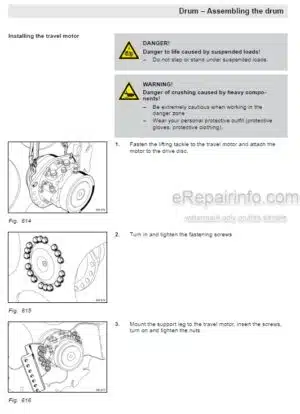
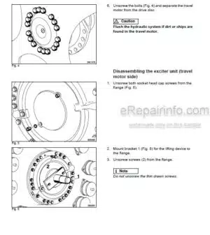
Removing And Installing The Drum
Repairing The Drum
Disassembling And Assembling The Change-Overweight
Changing The Rubber Buffers And Adjusting The Pretension
-OSCILLATING ARTICULATED JOINT
Special Tools, Oscillating Articulated Joint (BW177 To BW 216)
Repair Overview Oscillating Articulated Joint
Removing And Installing The Oscillating Articulated Joint
Dismantling The Oscillating Articulated Joint
Assembling The Oscillating Articulated Joint
-SUPPLIERS DOCUMENTATION
Travel Pump
Vibration Pump
Drum Drive
Vibration Motor
Axle Drive Motor
Steering Valve
Axle
-CIRCUIT DIAGRAMS
Hydraulic Diagram
Wiring Diagram
What you get
You will receive PDF file with high-quality manual on your email immediately after the payment.


Reviews
There are no reviews yet