


Factory Service Manual For Bomag Single Drum Roller. Manual Contains Illustrations, Instructions, Diagrams For Step By Step Remove And Install, Assembly And Disassembly, Service, Inspection, Repair, Troubleshooting, Tune-Ups.
Format: PDF
Language: ENG
Pages: 1324
Number: 00891693 (june 2012)
Bookmarks: Yes
Searchable: Yes
Wiring Diagrams: Yes
Model
Bomag Single Drum Roller
BW219DH-4
BW219PDH-4
BW226DH-4
BW226PDH-4
S/N 101 582 77 1516 >
S/N 101 582 78 1035 >
S/N 101 582 88 1035 >
S/N 101 582 89 1009 >
S/N 101 584 04 ….
S/N 101 584 05 ….
S/N 101 584 06 ….
S/N 101 584 07 ….
Contents
-GENERAL
Introduction
Safety Regulations
General Repair Instructions
Tightening Torques
-BOMAG SINGLE DRUM ROLLERS
Bomag Single Drum Rollers
-TECHNICAL DATA
Technical Data
-MAINTENANCE
General Notes On Maintenance
Fuels And Lubricants
Table Of Fuels And Lubricants
Running-In Instructions
Maintenance Table
-E-PLAN WIRING DIAGRAMS
Understanding Wiring Diagrams
Circuit Symbols In The Circuit Diagram
Identification Of Switch Blocks In The Wiring Diagram
Designation Of Components In The Wiring Diagram
Terminal Designations In Wiring Diagram
-ELECTRICS
Battery Ground And Analog Ground
Current And Voltage
Pulse Width Modulation (PWM)
Resistance
Series / Parallel Connection
Ohm’s Law
Electrical Energy
Formula Diagram
Metrology
Diodes, Relays, Fuses
Telemecanique Switch
Plug Connectors
Magnetic Coil Plug
Deutsch Plug, Series DT And DTM
Acceleration Transducer
Inductive Proximity Switches
Plugs And Terminals In Spring Clamping Technology
Batteries
Battery Service
Starting With Jump Wires
Main Battery Switch
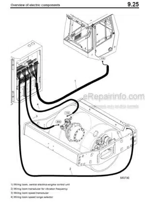
Overview Of Electric Components
Cabin
Fuses
Main Battery Fuse
Electronic Control Units
Checking The Voltage Supply For The Control Unit
Diagnostics Concept
-ELECTRONIC MODULES
Electrics SX
BEM, Bomag Evib-Meter
Electric Module A108
-ENGINE ELECTRICS
EMR3 System Components
Pin Assignment Of Engine Control Edc16 / Emr3
Rotary Speed Sensor For Camshaft
Crankshaft Speed Sensor
Rail Pressure Sensor
Fuel Pressure Sensor
Fuel Control Unit
Injector
Oil Pressure Sensor
Sensor For Charge Air Temperature And Charge Air Pressure
EMR Coolant Temperature Sensor
Glow Plugs
Sensor, Water In Fuel
Fuel Pre-Heating
Rotary Switch For Engine Speed
Data Collector
Fault Display
Diagnose With Serdia
Diagnose With Can-Bus
Diagnostics Interface
Emr3 List Of Fault Codes
Generator
Replacing The Voltage Regulator
Electric Starter
-HYDRAULICS
Hydraulic Circuit
Travel And Vibration Pump, H1
Troubleshooting Axial Piston Pumps
Travel Motor 51 C/D 110
Vibration Motor A2FM63 & A2FM80
Axial Piston Swash Plate Principle / Motor
Trouble Shooting, Variable Displacement Axial Piston Motor
External Gear Pumps
Travel Circuit
Stopping The Machine, Operating The Parking Brake
Towing In Case Of An Engine Failure
Towing In Case Of An Engine Failure
Adjust The Parking Brake
Vibration Circuit
Steering Circuit
Check The Hydraulic Oil Level
Changing Hydraulic Oil And Breather Filter
Replace Hydraulic Oil Filter
-TESTS AND ADJUSTMENTS
Special Tools, Tests And Adjustments
Activate Service Mode
Driving Against The Closed Brake
Check The Leakage Rate Of The Vibration Motor
Pressure Test In Steering Circuit
-FLUSHING AND BLEEDING
Special Tools For Flushing
Flushing – General
Flushing Schematic Travel Circuit (Distribution Travel Pump)
Flushing The Travel Circuit (Travel Pump Distribution)
Flushing Schematic Travel Circuit (Distribution Axle Motor)
Flushing The Travel Circuit (Axle Motor Distribution)
Flushing Schematic For Vibration Drive
Flushing The Vibration Circuit
Bleeding The Travel Circuit
Bleeding The Vibration Circuit
-582 502 15 DUST PROTECTION / 582 502 16 GASKET
Assembling The Dust Protection
-ENGINE
Diesel Engine
Engine Description TCD 2012
Lubrication Oil Circuit TCD 2012 / 2013
Coolant Circuit TCD 2012/2013
Fuel System TCD 2012/2013
Deutz Common Rail (Dcr) Injection System For TCD 2012 / 2013
Exhaust Gas Recirculation TCD 2012 / 2013
Wastegate – Charge Pressure Controller On TCD-Engines
Engine Problems
Check The Engine Oil Level
Change Engine Oil And Oil Filter Cartridge
Change The Fuel Pre-Filter Cartridge
Replace The Fuel Filter Cartridge
Check, Clean The Water Separator
Check The Coolant Level
Change The Coolant
Checking The Thermostat In Disassembled State
Service The Combustion Air Filter
Check The Dust Separator
Cleaning The Oil Bath Air Filter
Adjust The Valve Clearance
Checking / Replacing The Ribbed V-Belt
Check The Engine Mounts
Replacing The Crank Case Pressure Ventilation Valve
Engine Conservation
Special Tools, Deutz Engine (TCD 2012 2V)
-AIR CONDITIONING SYSTEM
Physical Basics
Refrigerant R134A
Compressor Oil / Refrigeration Oil
Working Principle Of The Air Conditioning System
Monitoring Devices
Description Of Components
Measuring The Compressor Oil Level
Checking The Magnetic Clutch
Inspection And Maintenance Work
Checking, Replacing The Refrigerant Compressor V-Belt
Service The Air Conditioning
Drying And Evacuation
Emptying In Case Of Repair
Leak Test
Filling Instructions
Trouble Shooting In Refrigerant Circuit, Basic Principles
Trouble Shooting, Refrigerant Circuit Diagram
Trouble Shooting Procedure
Steam Table For Rl34A
-CABIN ASSEMBLY
Preparations
Cabin Assembly
Final Function Tests And Checks
-REPLACING THE CAB WINDOW PANES
Assembly Of Window Panes
Special Tools, Cabin Windows
Auxiliary Materials
Removing And Installing The Window Pane
-DRUM
Special Tools, Drum, Single Drum Rollers
Repair Overview For Drum
Removing And Installing The Drum
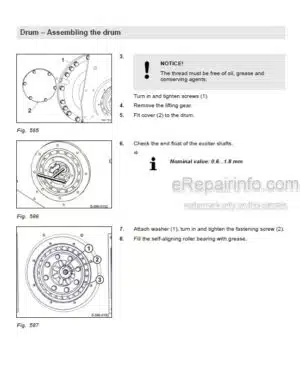
Repairing The Drum
Dismantling, Assembling The Change-Over Weights
Changing The Rubber Buffers And Adjusting The Pretension
-OSCILLATING ARTICULATED JOINT
Special Tools
Repair Overview Oscillating Articulated Joint
Removing And Installing The Oscillating Articulated Joint
Dismantling The Oscillating Articulated Joint
Assembling The Oscillating Articulated Joint
-SUPPLIERS DOCUMENTATION
Travel And Vibration Pump
Vibration Motor
Drum Reduction Gear
Axle Drive Motor
Axle
-CIRCUIT DIAGRAMS
Wiring Diagram
What you get
You will receive PDF file with high-quality manual on your email immediately after the payment.


Reviews
There are no reviews yet