


Factory Service Manual For Bomag Rubber Tire Roller. Manual Contains Illustrations, Instructions, Diagrams For Step By Step Remove And Install, Assembly And Disassembly, Service, Inspection, Repair, Troubleshooting, Tune-Ups.
Format: PDF
Language: ENG
Pages: 620
Number: 00891117 (march 2008)
Bookmarks: Yes
Searchable: Yes
Wiring Diagrams: Yes
Hydraulic Diagrams: Yes
Model
Bomag Rubber Tire Roller
BW24RH
BW27RH
S/N 101 538 00 ….
S/N 101 538 10 ….
Contents
-GENERAL
Introduction
Safety Regulations
General Repair Instructions
Tightening Torques
-MAINTENANCE
General Notes On Maintenance
Fuels And Lubricants
Table Of Fuels And Lubricants
Running-In Instructions
Maintenance Chart
-TECHNICAL DATA
Technical Data
-FUNDAMENTAL ELECTRICS
Understanding Circuit Diagrams
Terminal Designations
Battery Ground And Analog Ground
Current And Voltage
Can-Bus
Resistance
Series / Parallel Connection
Ohm’s Law
Electrical Energy
Formula Diagram
Metrology
Diodes, Relays, Fuses
Batteries
Three-Phase Generator
Electric Starter
Telemechanique Switch
Inductive Proximity Switches
Angle Sensors
Plug Connectors
Deutsch Plug, Series DT And DTM
Plugs And Terminals In Spring Clamping Technology
Electric Modules
-SPECIAL TOOLS, ELECTRICS
Special Tools, Electrics
-ELECTRONIC MODULES
Module Description A04
Module Description A100
-SPEEDOMETER MODULE
Speedometer Module
-ENGINE
Diesel Engine, General
Service Side
Starter Side
Compressor
Lubrication Oil Circuit
Oil Pressure Switch And Low Oil Pressure Circuitry
Check The Engine Oil Level
Changing Engine Oil And Oil Filter Cartridges
Coolant Circuit
Coolant Temperature Switch
Disassembling And Assembling The Coolant Temperature Switch
Replacing The Thermostat
Checking The Thermostat In Disassembled State
Check The Coolant Level
Change The Coolant
Clean The Cooling Fins On Engine And Hydraulic Oil Cooler
Three-Phase Generator
Checking / Replacing The Ribbed V-Belt
Check The Engine Mounts
Fuel Supply
Injection System
Injection Pump Replacement During Service
Injection Valve Replacement During Service
Checking / Repairing Injection Valves
Fuel Filter
Check, Clean The Water Separator
Change The Fuel Pre-Filter Cartridge
Change The Fuel Filter Cartridge
Checking The Compression
Check, Adjust The Valve Clearance
Boost Fuel Solenoid Valve
Engine Shut-Down Solenoid
Air Filter, Differential Pressure Switch
Combustion Air Filter Service
Heating Flange On Engine (Option)
Checking The Heating Flange Control
Engine Monitoring
Engine
Special Tools, Deutz Engine (BFM 2012)
-FRONT AXLE
Repair Overview For Front Axle
Dismantling The Front Axle
Assembling The Front Axle
-SERVICE TRAINING
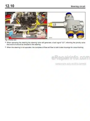
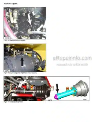
Service Training Hydraulics
-AIR CONDITIONING SYSTEM
Physical Basics
Refrigerant Rl34A
Compressor Oil / Refrigeration Oil
Working Principle Of The Air Conditioning System
Monitoring Devices
Description Of Components
Checking The Compressor Oil Level
Checking The Magnetic Clutch
Inspection And Maintenance Work
Checking, Replacing The Refrigerant Compressor V-Belt
Service The Air Conditioning
Drying And Evacuation
Emptying In Case Of Repair
Leak Test
Filling Instructions
Trouble Shooting In Refrigerant Circuit, Basic Principles
Trouble Shooting, Refrigerant Circuit Diagram
Trouble Shooting Procedure
Steam Table For R134A
Heating Control / Air Conditioning Control
-REPLACING THE CAB WINDOW PANES
Assembly Of Window Panes
Special Tools
Auxiliary Materials
Removing And Installing The Window Pane
-SUPPLIERS DOCUMENTATION
Travel Pump A4VG 71 … 180
Travel Motor A6VMA/E
Travel Gear
-CIRCUIT DIAGRAMS
Wiring Diagram
Hydraulic Diagram
Pneumatic Diagram
-SUPPLEMENT TO CIRCUIT DIAGRAM
Control Elements
Monitoring Board A15
Terminal Box
Engine Compartment
What you get
You will receive PDF file with high-quality manual on your email immediately after the payment.


Reviews
There are no reviews yet.