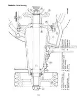
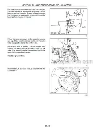
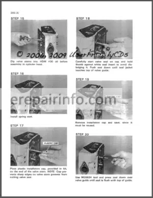
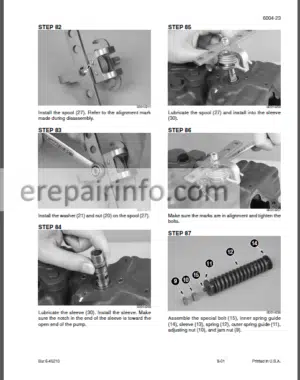
Factory Service Manual For Case Combine. Manual Contains Illustrations, Instructions, Diagrams For Step By Step Remove And Install, Assembly And Disassembly, Service, Inspection, Repair, Troubleshooting, Tune-Ups.
Format: PDF
Language: English
Pages: 357
Number: GSS1500
Bookmarks: Yes
Wiring Diagrams: Yes
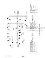
Hydraulic Diagrams: Yes
Model
Case Chassis Combine
1420 Axial Flow
Contents
SAFE WORK RULES
METRIC CONVERSION TABLE
STANDARD TORQUE DATA FOR NUTS AND BOLTS
STANDARD TORQUE DATA FOR HYDRAULIC TUBES AND FITTINGS
FLANGETTE BEARING INSTALLATION
SERVICE INFORMATION SYSTEM (S.I.S.)
SPECIAL SERVICE TOOLS REQUIRED
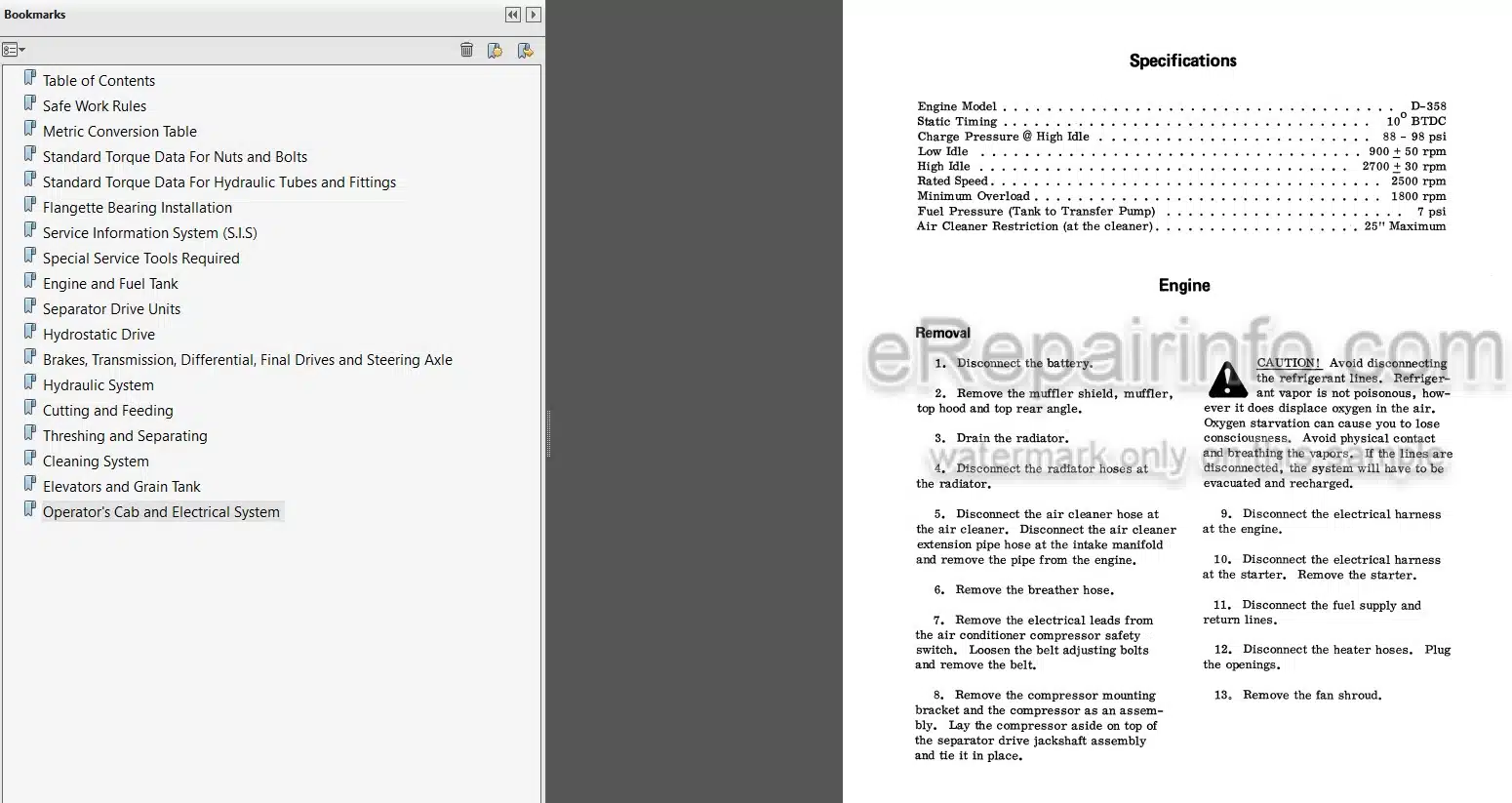
-ENGINE AND FUEL TANK
Engine
Removal
Fuel Tank
Fuel Tank Sending Unit
-SEPARATOR DRIVE UNITS
Engine PTO Gear Box
Separator Drive Jackshaft
-HYDROSTATIC DRIVE
Specifications
Hydrostatic Drive Schematic
Pump Control Arm Stop Adjustment
General Information
Test Procedures
Hydrostatic Drive Pump
Hydrostatic Drive Motor
Foot-N-Inch Valve
Flushing and Bleeding the Propulsion Drive System
-BRAKES, TRANSMISSION, DIFFERENTIAL, FINAL DRIVES AND STEERING AXLE
General Description
Specifications
Ground Travel Speed Chart and Calibration Setting
Transmission
Final Drive and Pinion Assembly
Brakes
Guide Wheel Axle
-HYDRAULIC SYSTEM
Hydrostatic Power Steering
Electro-Hydraulic Control Valves
Automatic Header Control
Accumulator
Header Lift Cylinders
Swing Cylinder
Reel Lift Master and Slave Cylinders
Feeder or Separator Clutch Cylinder
Hydraulic Reel Drive or Windrow Pick-up Drive
Hydraulic Pump
Reservoir
Flushing, Cleaning and Purging the Hydraulic System
-CUTTING AND FEEDING
Specifications
Feeder Gear Housing Assembly
-THRESHING AND SEPARATING
Rotor Drive Gear Case and Torque Sensing Unit
Rotor
Rotor Front Bearing Replacement
Auger Bed Assembly
Discharge Beater
Straw Chopper
Combine Performance Check
Corn Loss Tables
Seed Loss Tables
Troubleshooting – Threshing and Separation Problems
-CLEANING SYSTEM
Cleaning Fan
Variable Speed Fan Drive
-ELEVATORS AND GRAIN TANK
Grain Tank Unloader Vertical Auger
Unloader Control Adjustment
Unloader Lower Gear Case Assembly
Unloader Upper Gear Case Assembly Elevator Drive Jackshaft
-OPERATOR’S CAB AND ELECTRICAL SYSTEM
General Description
Servicing the Components
Air Conditioning System
Shaft Speed Monitoring System
Wiring Diagrams
Wiring Diagrams — Cont’d
Electrical Specifications
What you get
You will receive PDF file with high-quality manual on your email immediately after the payment.




Reviews
There are no reviews yet.