


Factory Technical and Workshop Manuals For Hitachi Hitachi EX27U North America EX35U North America Excavators. Tons of illustrations, instructions, diagrams for step by step remove and install, assembly and disassembly, service, inspection, repair, troubleshooting, tune-ups.
Format: PDF
Language: English
Pages: 539
Bookmarks: Yes
Searchable: Yes
Wiring Diagrams: Yes
Hydraulic Diagrams: Yes
Model
Hitachi EX27U-North America, EX35U-North America
Contents
1.Technical Manual
-GENERAL
–SPECIFICATION
Specifications
Working Ranges and Machine Dimensions for Transportation
Engine Specification
Interchangeability
–COMPONENT LAYOUT
Main Component
Electrical System
Relays
Monitor and Switches
-SYSTEM
–HYDRAULIC SYSTEM
Outline
Main Circuit
Pilot Circuit
-COMPONENT OPERATION
–PUMP DEVICE
Outline
Main Pump (P1, P2)
Main Pump (P3), Pilot Pump (P4) (30u, 35u)
Pilot Pump (P4) (27u)
Horse Power Control Operation
–SWING DEVICE
Outline
Swing Motor
Parking Brake
Valve Unit
Swing Reduction Gear
–CONTROL VALVE
Outline
Hydraulic Circuit
Boom Anti-Drift Valve
Main Circuit Switch Valve (27u)
Flow Combiner Valve (35u)
Arm Regenerative Valve
Main Relief Valve
Overload Relief Valve
Make-Up Valve
–PILOT VALVE
Outline
Operation
–TRAVEL DEVICE
Outline
Travel Motor
Travel Brake Valve
Travel Reduction Gear
–OTHERS (UPPERSTRUCTURE)
Solenoid Valve
Pilot Relief Valve
–OTHERS (UNDERCARRIAGE)
Swing Bearing
Center Joint
Track Adjuster
-OPERATIONAL PERFORMANCE TEST
–INTRODUCTION
Operational Performance Test
Preparation for Performance Tests
–ENGINE TEST
Engine Speed
Engine Compression Pressure
Valve Clearance
Nozzle Check
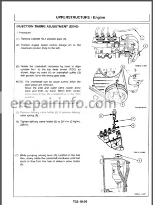
Injection Timing
–EXCAVATOR TEST
Travel Speed
Track Revolution Speed
Mistrack Check
Travel Motor Leakage
Swing Speed
Swing Function Drift Check
Swing Motor Leakage
Maximum Swingable Slant Angle
Swing Bearing Play
Hydraulic Cylinder Cycle Time
Dig Function Drift
Control Lever Operating Force
Control Lever Stroke
–COMPONENT TEST
Primary Pilot Pressure
Secondary Pilot Pressure
Main Relief Valve Set Pressure
Overload Relief Valve Set Pressure
Pump Driving Torque
Swing Motor Drainage
Travel Motor Drainage
–STANDARD
Operational Performance Standard
-TROUBLESHOOTING
–DIAGNOSING PROCEDURE
Introduction
Diagnosing Procedure
–TROUBLESHOOTING A
Troubleshooting A Procedure
Engine system Troubleshooting
Actuator Operating System
Troubleshooting
Front Attachment System
Troubleshooting
Swing System Troubleshooting
Travel System Troubleshooting
Blade System Troubleshooting
How to Lower Boom When Engine Stops
–TROUBLESHOOTING B
Troubleshooting B Procedure
Malfunction of Coolant Temperature Gauge
Malfunction of Fuel Gauge
Malfunction of Alternator Indicator
Malfunction of Engine Oil Pressure Indicator
Malfunction of Overheat Indicator
Malfunction of Fuel Level Indicator
Malfunction of Buzzer
Malfunction of Hour Meter
–ELECTRICAL SYSTEM INSPECTION
Precautions for Inspection and Maintenance
Fuse Continuity Test
Battery Voltage Check
Voltage Check
Continuity Check
-ALL DIAGRAMS
EX27u Hydraulic Circuit Diagram
EX35u Hydraulic Circuit Diagram
EX27u, 35u Hydraulic Circuit Diagram
2.Workshop Manual
-GENERAL INFORMATION
–PRECAUTIONS FOR DISASSEMBLING AND ASSEMBLING
Precautions for Disassembling and Assembling
–TIGHTENING
Tightening Torque Specifications
Torque Chart
Piping Joint
-UPPERSTRUCTURE
–CANOPY
Remove and Install Canopy
–COUNTERWEIGHT
Remove and Install Counterweight
–PUMP DEVICE
Remove and Install Pump Device
Disassemble Pump Device(27u)
Assemble Pump Device(27u)
Disassemble Pump Device(35u)
Assemble Pump Device(35u)
Maintenance Standards
–CONTROL VALVE
Remove and Install Control Valve
Disassemble and Assemble
Control Valve
–SWING DEVICE
Remove and Install Swing Device
Disassemble Swing Reduction Gear
Assemble Swing Reduction Gear
Disassemble Swing Motor
Assemble Swing Motor
Maintenance Standards
–PILOT VALVE
Remove and Install Pilot Valve
Disassemble Pilot Valve
Assemble Pilot Valve
–SOLENOID VALVE
Disassemble and Assemble
Solenoid Valve
–ROTARY VALVE
Remove and Install Rotary Valve
Disassemble Rotary Valve
Assemble Rotary Valve
-UNDERCARRIAGE
–SWING BEARING
Remove and Install Swing Bearing
–TRAVEL DEVICE
Remove and Install Travel Device
Disassemble Travel Device(27u)
Assemble Travel Device(27u)
Disassemble Travel Device( 35u)
Assemble Travel Device(35u)
Maintenance Standards
–CENTER JOINT
Remove and Install Center Joint
Disassemble Center Joint
Assemble Center Joint
–TRACK ADJUSTER
Remove and Install Track Adjuster
–FRONT IDLER
Remove and Install Front Idler
Maintenance Standards
–UPPER AND LOWER ROLLER
Remove and Install Upper Roller
Remove and Install Lower Roller
Maintenance Standards
–TRACK
Remove and Install Rubber Track
Maintenance Standards
-FRONT ATTACHMENT
–FRONT ATTACHMENT
Remove and Install Front Attachment
Maintenance Standards
–CYLINDER
Remove and Install Cylinders
Disassemble Boom Cylinder and Arm Cylinder
Assemble Boom Cylinder and Arm Cylinder
Disassemble Bucket Cylinder and Blade Cylinder
Assemble Bucket Cylinder and Blade Cylinder
Disassemble Swing Cylinder
Assemble Swing Cylinder
Maintenance Standards
-ENGINE
–GENERAL INFORMATION
General Repair Instruction
Notes On The Format Of This Manual
Appearance
Main Data And Specifications
Tightening Torque Specifications
Angular Nut And Bolt
Tightening Method
Tightening Torque On
Major Components
Gasket Locat;On
Maintenance
Recommended Jbricating Oil
–ENGINE
General View Of Engine
Disassembly
Inspection And Repair
Reassembly
–LUBRICATION SYSTEM
Lubricating Oil Circulation
System Diagram
Oil Pump
–COOLING SYSTEM
Cooling Water Circulation System Diagram
Water Pump
Thermostat
–FUEL SYSTEM
Fuel Circulation System Diagram
Governor
Nozzle Holder Assembly
–TROUBLESHOOTING
–SPECIAL TOOL
–CONVERSION TABLE
Length
Area
Volume
Mass
Pressure
Torque
Temperature
What you get
You will receive PDF file with high-quality manual on your email immediately after the payment.


Reviews
There are no reviews yet.