Factory Technical Manual and Workshop Manual For Hitachi EX45 Excavators. Tons of illustrations, instructions, diagrams for step by step remove and install, assembly and disassembly, service, inspection, repair, troubleshooting, tune-ups.
Format: PDF
Language: English
Pages: 568
Bookmarks: Yes
Searchable: Yes
Number: KM510E-01
Wiring Diagrams: Yes
Hydraulic Diagrams: Yes
Model
Hitachi EX45
Contents
1.Technical Manual
INTRODUCTION
SAFETY
-SPECIFICATIONS
–GENERAL INFORMATION
Outline
Specifications
Working Range
Lifting Capacities
Service Refill Capacities
–DIMENSIONS AND WEIGHTS
Transportation
Weight
–FUELS AND LUBRICANTS
Fuel
Engine Oil
Hydraulic Oil
Gear Oil
Grease
Engine Coolant
–INTERCHANGEABILITY
Interchangeability
-UPPERSTRUCTURE
–OUTLINE
Upperstructure Outline
–TANKS
Construction
–PUMP DEVICE
Construction and Function
–SWING DEVICES
Construction and Function
Swing Reduction Device
Swing Motor
Swing Brake Valve
Overload Relief Valve
–PIPINGS
General
–CONTROL VALVE
General
Switch Valve
Main Relief Valve
Overload Relief Valve
–PILOT VALVE
Construction
Function
–PILOT SHUT-OFF VALVE
Construction and Function
–SOLENOID VALVE
Construction and Function
–ENGINE
Construction and Function
Radiator
Air Cleaner
Maintenance and Adjustment
-UNDERCARRIAGE
–OUTLINE
Undercarriage Outline
–SWING BEARING
Construction and Function
–CENTER JOINT
Construction and Function
–TRAVEL DEVICE
Construction and Function
Travel Reduction Gear
Travel Motor
Travel Brake Valve
Travel Speed Change Valve
Counterbalance Valve Operation
Overload Relief Valve Operation
–ADJUSTER
Construction and Function
-ELECTRICAL SYSTEM
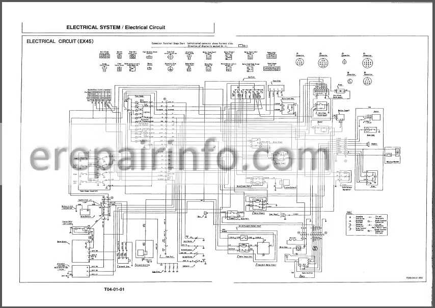
–ELECTRICAL CIRCUIT
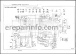
Electric Wiring Diagram
-HYDRAULIC SYSTEM
–HYDRAULIC CIRCUIT
Hydraulic Circuit Diagram
-OPERATIONAL PERFORMANCE TEST
–INTRODUCTION
Purpose
Terminology
Preparation For Performance Tests
–ENGINE TEST
Engine Speed
Engine Compression Pressure
–EXCAVATOR TEST
Travel Speed
Track Revolution Speed
Mistrack Check
Travel Motor Leak Check
Swing Speed
Swing Function Drift Check
Swing Motor Leakage
Swing Bearing Play
Hydraulic Cylinder Cycle Time
Dig Function Drift Check
Control Lever Operating Force
Control Lever And Pedal Stroke
–HYDRAULIC COMPONENT TEST
Pilot Secondary Pressure
Main Relief Valve Pressure Setting
Overload Relief Valve Pressure Setting
Swing Motor Overload Relief Valve Pressure Test
-TROUBLESHOOTING
–DIAGNOSING PROCEDURE
Introduction
Diagnosing Procedure
How to read the troubleshooting flow charts
Check Battery Voltage
–HYDRAULIC SYSTEM
Actuators
Front Attachments
Swing
Travel
–ELECTRICAL SYSTEM
Monitor Panel and Electrical Parts
Engine
Fuse Fails
Monitor Panel
Malfunction of Coolant Temperature Gauge
Malfunction of Fuel Gauge
Malfunction of Alternator
Indicator
Malfunction of Engine Oil Pressure Indicator
Malfunction of Overheat Indicator
Malfunction of Fuel Level Indicator
Malfunction of Air Filter Restriction Indicator
Malfunction of Buzzer
Malfunction of Hour Meter
Wiring Hamess Test
2.Workshop Manual
-SPECIFICATIONS
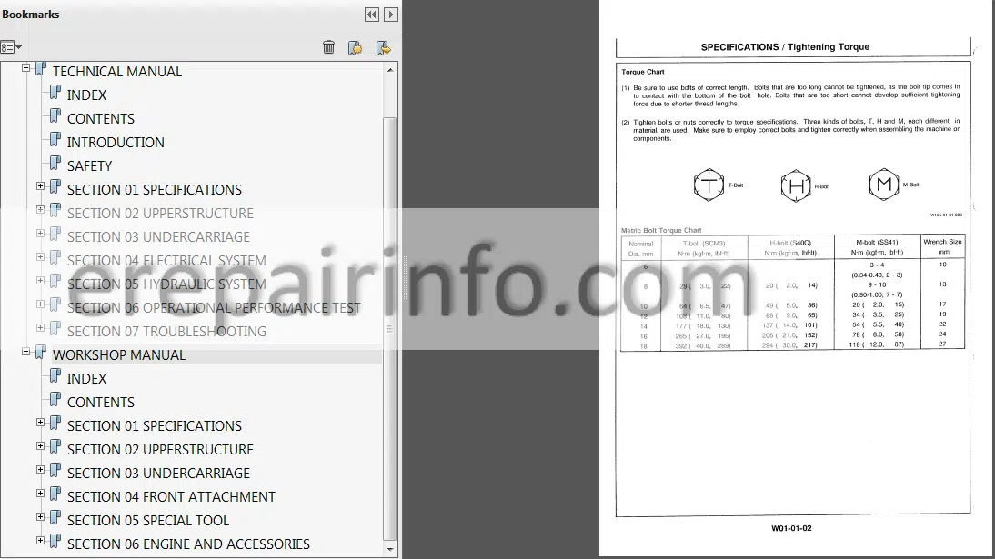
–TIGHTENING TORQUE
Tightening Torque
–LABELS
Label Location
-UPPERSTRUCTURE
–CAB
Removal and Installation
–COUNTERWEIGHT
Removal and Installation
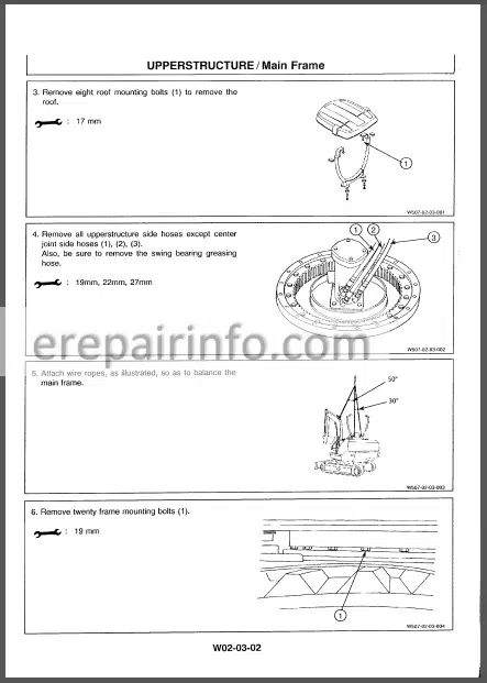
–MAIN FRAME
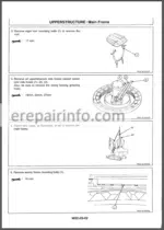
Removal and Installation
–PUMP DEVICE
Removal and Installation of Pump Device
Disassembly and Assembly of Pump Device
Maintenance Standard
–CONTROL VALVE
Removal and Installation of Control Valve
Disassembly and Assembly of Control Valve
–SWING DEVICE
Removal and Installation of Swing Device
Disassembly and Assembly of Swing Device
Maintenance Standard
–PILOT VALVE
Removal and Installation of Pilot Valve
Disassembly and Assembly of Pilot Valve
–SOLENOID VALVE
Disassembly and Assembly of Solenoid Valve
-UNDERCARRIAGE
–SWING BEARING
Removal and Installation
–TRAVEL DEVICE
Removal and Installation of Travel Device
Disassembly and Assembly of Travel Device
Maintenance Standard
–CENTER JOINT
Removal and Installation of Center Joint
Disassembly and Assembly of Center Joint
–TRACK ADJUSTER
Removal and Installation of Track Adjuster
–FRONT IDLER
Removal and Installation of Front Idler
Maintenance Standard
–CARRIER AND TRACK ROLLER
Removal and Installation of Carrier Roller
Removal and Installation of Track Roller
Maintenance Standard
–TRACK LINK
Removal and Installation of Track Link Assembly
Maintenance Standard
-FRONT ATTACHMENT
–FRONT ATTACHMENT
Removal and Installation of Front Attachment
Maintenance Standard
–CYLINDER
Removal and Installation of Cylinder
Disassembly and Assembly of Cylinder
Maintenance Standard
-SPECIAL TOOL
–SPECIAL TOOL
Drawing Of Special Tool
-ENGINE AND ACCESSORIES – EX45(ISUZU 4JC1)
–GENERAL INFORMATION
General Repair Instruction
Notes On The Format Of This Manual
Main Data And Specifications
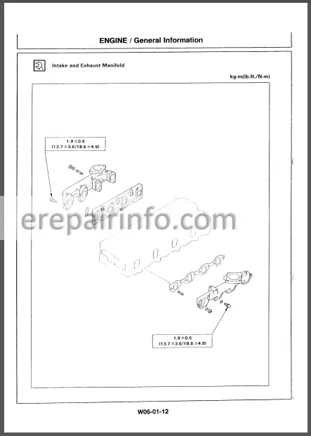
Tightening Torque Specifications
–MAINTENANCE
Model Identification
Injection Pump Identification
Lubricating System
Fuel System
Cooling System
Valve Clearance Adjustment
Injection Timing
Compression Pressure Measurement
Recommended Lubricants
Repair Kit
–ASSEMBLY I
General Description
Disassembly Steps-1
Disassembly Steps-2
Disassembly Steps-3
Disassembly Single Unit
–ASSEMBLY II
Inspection And Repair
Cylinder Head
Valve Guide
Valve And Valve Seat Insert
Valve Spring
Rocker Arm Shaft And
Rocker Arm
Cylinder Body
Tappet And Push Rod
Camshaft
Crankshaft And Bearing
Crankshaft Pilot Bearing
Flywheel And Ring Gear
Piston Ring
Piston Pin
Connecting Rod
Idler Gear Shaft And Idler Gear
–ASSEMBLY III
Reassembly Single Unit
Reassembly Steps-1
Reassembly Steps-2
Reassembly Steps-3
–LUBRICATING SYSTEM
Main Data And Specifications
General Description
Oil Pump
Oil Filter With Built-In Oil Cooler
–COOLING SYSTEM
Main Data And Specifications
General Description
Water Pump
Thermostat
–FUEL SYSTEM
Main Data And Specifications
General Description
Injection Nozzle
Injection Pump Data
–TROUBLESHOOTING
Hard Starling
Unstable Idling
Insufficient Power
Excessive Fuel Consumption
Excessive Oil Consumption
Overheating
White Exhaust Smoke
Dark Exhaust Smoke
Oil Pressure Doos Not Rise
Abnormal Engine Noise
–SPECIAL TOOL
Special Tool List
What you get
You will receive PDF file with high-quality manual on your email immediately after the payment.

Reviews
There are no reviews yet.