


Factory Service Repair Manuals set For Hitachi Zaxis 210W Excavators. Tons of illustrations, instructions, diagrams for step by step remove and install, assembly and disassembly, service, inspection, repair, troubleshooting, tune-ups.
Format: PDF
Language: English
Pages: 1526
Number: KM-CDBE
Wiring Diagrams: Yes
Hydraulic Diagrams: Yes
Model
Hitachi Zaxis 210W
Contents
1.Technical Manual
2.Workshop Manual
INTRODUCTION
sAFETY
-GENERAL INFORMATION
–PRECAUTIONS FOR DISASSEMBLING AND ASSEMBLING
Precautions for Disassembling and Assembling
Maintenance Standard Terminology
–TIGHTENING TORQUE
Tightening Torque Specification
Torque Chart
Piping Joint
Periodic Replacement of Parts
–PAINTING
Painting
–BLEEDING AIR FROM HYDRAULIC OIL TANK
Bleeding Air from Hydraulic Oil tank
-UPPERSTRUCTURE
–CONTROL VALVE
Remove and Install Control Valve
Disassemble Control Valve (4-Spool Section)
Disassemble Control Valve (5-Spool Section)
Disassemble and Assemble 4-Spool and 5-Spool Sections
Assemble Control Valve (4-Spool Section)
Assemble Control Valve (5-Spool Section)
Remove and Install
Auxiliary Control Valve
Disassemble Auxiliary Control Valve Assemble Auxiliary Control Valve
–SWING DEVICE
Remove and Install Swing Device
Disassemble Swing Reduction Gear
Assemble Swing Reduction Gear
Disassemble Swing Motor
Assemble Swing Motor
Maintenance Standard
–PILOT VALVE
Remove and Install Pilot Valve
Disassemble Front/Swing Pilot Valve
Assemble Front/Swing Pilot Valve
Disassemble Travel, PositionIng/Auxillary
Blade/Stabilizer Pilot Valve
Assemble Travel, Positioning/Auxiliary Blade/Stabilizer Pilot Valve
–PILOT SHUT-OFF VALVE
Remove and Install Pilot Shut-Off Valve
Disassemble Pilot Shut-Off Valve
Assemble Pilot Shut-Off Valve
–SIGNAL CONTROL VALVE
Remove and Install Signal Control Valve
–TRAVEL SHOCKLESS VALVE
Remove and Install Travel Shockless Valve
Construction of Travel Shockless Valve
–SOLENOID VALVE
Remove and Install 4-Unit Solenoid Valve Unit
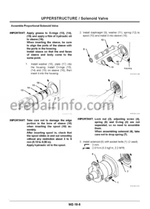
Disassemble Proportional Solenoid Valve
Assemble Proportional Solenoid Valve
Remove and Install 2-Unit Solenoid Valve (for Pump Control)
Construction of 2-Unit Solenoid Valve (for Pump Control)
Remove and Install 2-Unit Solenoid Valve (for Blade/Stabilizer)
Construction of 2-Unit Solenoid Valve (for Blade/Stabilizer)
–PILOT RELIEF VALVE
Remove and Install Pilot Relief Valve
Construction of Pilot Relief Valve
–STEERING VALVE
Remove and Install Steering Valve
Disassemble Steering Valve
Assemble Steering Valve
–BRAKE VALVE
Remove and Install Brake Valve
Disassemble Brake Valve
Assemble Brake Valve
–ACCUMULATOR CHARGING VALVE
Remove and Install
Accumulator Charging Valve
Constructton of
Accumulator Charging Valve
–TRANSMISSION CONTROL VALVE
Remove and Install
Transmission Control Valve
Construction of
Transmission Control Valve
-UNDERCARRIAGE
–SWING BEARING
Remove and Install Swing Bearing
Disassemble Swing Bearing
Assemble Swing Bearing
–TRAVEL MOTOR
Remove and Install Travel Motor
Disassemble Travel Motor
Assemble Travel Motor
Disa sse тџе Bra ke Va Ive
Assemble Brake Valve
–CENTER JOINT
Remove and Install Center Joint
Disassemble Center Joint
Assemble Center Joint
Maintenance Standard
–TRANSMISSION
Rernuve and Inslall Tiarisrnission
Disassemble Transmission
Disassemble Final Drive and Differential
Assemble Final Drive and Differential
Assemble Transmission
Adjusting Gear Clearance
–AXLE
Remove and Install Axle
Disassemble Front Axle
Assemble Front Axle
Disassemble Rear Axle
Assemble Rear Axle
Disassemble Differential
Assemble Differential
Disassemble Steering Cylinder
Assemble Steering Cylinder
–AXLE LOCK CYLINDER
Remove and Install Axle Lock Cylinder
Disassemble and Assemble
Axle Lock Cylinder
–OPERATE-CHECK VALVE
Remove and Install Operate-Check Vatve (for Axle Lock Cylinder)
Construction of Operate-Check
Valve (for Axle Lock Cylinder)
–PROPELLER SHAFT
Remove and Install Propeller Shaft
-FRONT ATTACHMENT
–FRONT ATTACHMENT
Hydraulic Circuit Pressure Release Procedure
Remove and Install Mono block Boom Front Attachment
Remove and Install 2-Piece Boom Front Attachment
Maintenance Standard
Standard Dimensions for Arm and Bucket Connection
Standard Dimensions for Arm and Boom Connection
–CYLINDER
Remove and Install Cylinder(Monoblock Boom, 2-Piece Boom)
Disassemble Cylinder (Boom (ћопоџоск/2-Piece),Positioning, Bucket)
Assemble Cylinder (Boom (ћопоџоск/2-Piece), Positioning, Bucket)
Disassemble Cylinder (Arm)
Assemble Cylinder (Arm)
Disassemble Cylinder (Stabilizer, Blade)
Assemble Cylinder (Stabilizer, Blade)
Maintenance Standard
–HOSE-RUPTURE SAFETY VALVE
Remove and Install
Hose-Rupture Safety Valve
Construction of
Hose-Rupture Safety Valve
–OPERATE-CHECK VALVE
Remove and Install Operate-Check Valve (for Blade/Stabilizer)
Construction of Operate-Check Valve (for Blade/Stabilizer)
-ENGINE AND ACCESSORY
–GENERAL INFORMATION
General Repair Instructions
Notes on the Format of This Manual
Main Data and Specifications
Performance Curve
External View
Tightening Torque Specifications
Angular Nut and Bolt Tightening Method
Major Parts Fixing Nuts and Bolts
Identifications
–MAINTENANCE
Lubricating System
Fuel System
Cooling System
Valve Clearance Adjustment
Injection Timing
Compression Pressure Measurement
TnrhrvhargAr IrHSportinn
Engine Repair Kit
Recommended Lubricants
Engine Oil Viscosity Chart
–ENGINE ASSEMBLY 1 (DISASSEMBLY)
External Parts Disassembly Steps
Major Components
Rocker Arm and Rocker Arm Shaft
Disassembly Steps
Cylinder Head Disassembly Steps
Piston and Connecting Rod
Disassembly Steps
–ENGINE ASSEMBLY 2 (INSPECTION AND REPAIR)
Cylinder Head
Valve Guide
Valve Spring
Tappet
Push Rod
Rocker Arm Shaft and Rocker Arm
Idler Gear and Idler Gear Shaft
Camshaft
Cylinder Body and Liner
Piston and Piston Ring
Piston Pin
Connecting Rod
Crankshaft
Flywheel
Timing Gear Case Cover
–ENGINE ASSEMBLY 3 (REASSEMBLY)
Piston and Connecting Rod
Reassembly Steps
Cylinder Head Reassembly Steps
Rocker Arm and Rocker Arm Shaft
Reassembly Steps
Major Component Reassembly Steps 1
Major Component Reassembly Steps 2
External Parts Reassembly Steps (Left-Hand Side)
External Parts Reassembly Steps (Right-Hand Side)
Engine Tuning Operation
–LUBRICATING SYSTEM
General Description
Oil Pump
Oil Cooler
–COOLING SYSTEM
General Description
Thermostat
–FUEL SYSTEM
General Description
Injection Nozzle
Injection Pump Calibration Data
–TURBOCHARGER
General Description
Turbocharger Identification
Troubleshooting
Inspection and Repair
–ENGINE ELECTRICALS
Starter Identification
Starter Main Data and Specifications
Starter Sectional View
Performance
Disassembly
Inspection and Repair
Reassembly
Adjustment
Performance Test
Alternator Identification
Main Data and Specifications
Alternator Sectional View
Charging Circuit
Structure
Disassembly
Inspections
Reassembly
Bench Test
Current Output Test
Fault Finding
Specifications
–TROUBLESHOOTING
Hard Starting
1)Starter Inoperative
2)Starter Operates but
Engine does not Turn Over
3)Engine Turns Over but does not Start
Fuel is Being Delivered to the Injection Pump
4)Engine Turns Over but does not Start
Unstable Low Idling
Insufficient Power
Excessive Fuel Consumption
Excessive Oil Consumption
Overheating
Whity Exhaust Smoke
Dark Exhaust Smoke
Oil Pressure does not Rise
Abnormal Engine Noise
–SPECIAL TOOL LIST
Special Tool List
–REPAIR STANDARDS
Repair Standards
–CONVERSION TABLE
Length
Area
Volume
Mass
Pressure
Torque
Temperature
What you get
You will receive PDF file with high-quality manual on your email immediately after the payment.


Reviews
There are no reviews yet.