


Factory Technical Manuals and Workshop Manual Manual For Hitachi ZAXIS 450 450H 450LCH 460LCH Hydraulic Excavator. Tons of illustrations, instructions, diagrams for step by step remove and install, assembly and disassembly, service, inspection, repair, troubleshooting, tune-ups.
Format: PDF
Language: English
Pages: 628
Bookmarks: No
Searchable: Yes
Wiring Diagrams: Yes
Hydraulic Diagrams: Yes
Model
Hitachi Zaxis 450, 450H, 450LC, 450LCH, 460LCH
Contents
1.Technical Manual(Operation Principle)
2.Technical Manual(Troubleshooting)
3.Workshop Manual
4.Circuits
1.Technical Manual(Operation Principle)
INTRODUCTION
-GENERAL
–SPECIFICATION
Specifications
Working Ranges
–COMPONENT LAYOUT
Main Components Layout
Electrical Component Layout (Overview)
Electrical System (Relays and Related Equipment)
Electrical System (Monitors and Switches)
Engine
Pump Device
Swing Device
Control Valve
Signal Control Valve
Solenoid Valve Unit
Travel Device
–COMPONENT SPECIFICATIONS
Engine
Engine Accessories
Hydraulic Component
Electrical Component
-SYSTEM
–CONTROL SYSTEM
Outline
Engine Control
Pump Control
Valve Control
Other Controls
–HYDRAULIC SYSTEM
Outline
Pilot Circuit
Main Circuit
–ELECTRICAL SYSTEM
Outline
Main Circuit
Electric Power Circuit (Key Switch: OFF)
Indicator Light Check Circuit (Key Switch: ON)
Accessory Circuit
Preheat Circuit (Key Switch: Heat)
Starting Circuit (Key Switch: Start)
Charging Circuit (Key Switch: ON)
Serge Voltage Prevention Circuit
Engine Stop Circuit
–PUMP DEVICE
Outline
Main Pump
Regulator
Pilot Pump
N Sensor (Engine Speed Sensor)
Pump Delivery Pressure Sensor
Pump Displacement Angle Sensor
–SWING DEVICE
Outline
Swing Reduction Gear
Swing Motor
Swing Parking Brake
Valve Unit
–CONTROL VALVE
Outline
Hydraulic Circuit
Flow Combiner Valve
Main Relief Valve
Overload Relief Valve
Make-Up Valve
Holding Valve
Arm Regenerative Valve
Bypass Shut-Out Valve
Boom Overload Relief Selector Valve
–PILOT VALVE
Outline
Operation
–TRAVEL DEVICE
Outline
Travel Reduction Gear
Travel Motor
Travel Brake Valve
Travel Speed Control
Parking Brake
–SIGNAL CONTROL VALVE
Outline
Pilot Port
Shuttle Valve
Shockless Valve
Pump 1 and Pump 2 Flow Rate
Control Valves
Bucket Flow Rate Control Valve, Flow Combiner Valve Control Spool, Swing Parking Brake Release Spool
–OTHERS (UPPERSTRUCTURE)
Pilot Shut-Off Valve
Solenoid Valve Unit
Pilot Relief Valve
Accumulator
EC Motor
Distribution Valve
–OTHERS (UNDERCARRIAGE)
Swing Bearing
Center Joint
Track Adjuster
2.Technical Manual(Troubleshooting)
INTRODUCTION
SAFETY
-OPERATIONAL PERFORMANCE TEST
–INTRODUCTION
Operational Performance Tests
Preparation for Performance Test
–STANDARD
Operational Performance Standard Table
Main Pump P-Q Diagram
Injection Pump
DrZX Monitor Indicating Values
Sensor Activating Range
–ENGINE TEST
Engine Speed
Engine Compression Pressure
Valve Clearance Adjustment
Nozzle Check
Injection Timing
–EXCAVATOR TEST
Travel Speed
Track Revolution Speed
Mistrack Check
Travel Motor Leakage
Swing Speed
Swing Function Drift Check
Swing Motor Leakage
Maximum Swingable Slant Angle
Swing Bearing Play
Hydraulic Cylinder Cycle Time
Dig Function Drift Check
Control Lever Operating Force
Control Lever Stroke
Boom Raise/Swing Combined
Operation Check
–COMPONENT TEST
Primary Pilot Pressure
Secondary Pilot Pressure
Main Relief Pressure Shift Control Pressure(SA Pressure)
Travel Mode Shift Control Pressure(SB Pressure)
Boom Mode Selector Control Pressure(SC Pressure)
Main Pump Delivery Pressure
Main Relief Pressure
Overload Relief Valve Set Pressure
Main Pump Flow Rate Measurement
Swing Motor Drainage
Travel Motor Drainage
–ADJUSTMENT
Installation and Adjustment of Pump Displacement Angle Sensor
Engine Speed Adjustment and Engine Learning
Check of Governor Lever and Fuel Cut Lever Position
-TROUBLESHOOTING
–GENERAL
Introduction
Diagnosing Procedure
Built-In Diagnosing System Operation
Built-In Diagnosing Function Display List
Dr ZX Operation
Dr ZX Fault Code List
Dr ZX Monitoring Item List
Dr ZX Special Function
Dr ZX Service Mode
Adjustment D3ta List
Binary Number Bit List
–COMPONENT LAYOUT
Main Component Layout
Electrical Component Layout (Overview)
Electrical System (Relays and Related Equipment)
Electrical System (Monitors 3nd Switches)
Engine
Pump Device
Swing Device
Control V3lve
Signal Control Valve
Solenoid Valve Unit
Travel Device
Components in Control Valve
Signal Control Valve Port Location
–TROUBLESHOOTING A
Troubleshooting A Procedure
Fault Code List
Fault Code 01, 02, 03
Fault Code 04
Fault Code 05
Fault Code 06
Fault Code 07
Fault Code 08, 09
Fault Code 10, 11
Fault Code 12, 13
Fault Code 14, 15, 16, 18
Fault Code 19
Fault Code 20, 21
–TROUBLESHOOTING B
Troubleshooting B Procedure
Relationship between Machine Trouble Symptoms and Related Parts
Correlation between Trouble Symptoms and Part Failures
Engine System Troubleshooting
All Actuator System Troubleshooting
Front Attachment System Troubleshooting
Swing System Troubleshooting
Travel System Troubleshooting
Other System Troubleshooting
Charge Air Conditioner with Refrigerant
Exchange Inspection
–TROUBLESHOOTING C
Troubleshooting C Procedure
Malfunction of Coolant Temperature Gauge
Malfunction of Fuel Gauge
Malfunction of Indicator Light Check System
Malfunction of Preheat Indicator
Malfunction of Engine Oil Level Indicator
Malfunction of Coolant Level Indicator
Malfunction of Alternator Indicator
Malfunction of Engine Oil Pressure Indicator
Malfunction of Overheat Indicator
Malfunction of Air Filter Restriction Indicator
Malfunction of Fuel Level Indicator
Malfunction of Auto-Acceleration Indicator
Malfunction of Auto-Idle Indicator
Malfunction of Digging Mode Indicator, Trench Mode Indicator or Attachment Mode Indicator
Malfunction of Buzzer
Malfunction of LCD
Malfunction of Hour Meter
–ELECTRICAL SYSTEM INSPECTION
Precautions for Inspection and Maintenance
Instructions for Disconnecting Connectors
Fuse Inspection
Fusible Link Inspection
Battery Voltage Check
How to Troubleshoot Alternator Malfunctions
Continuity Check
Voltage and Current Measurement
Check by False Signal
Test Harness
–ICX
Outline
ICX Fault Code List
Satellite Terminal Fault Code List
Fault Code 1 to 6
Fault Code 7 to 10
Some Parts of Data in Daily Report, Frequency Distribution, Cumulative Operation Hours are not Recorded
Troubleshooting and Setting of ICX and Satellite Terminal Using Dr ZX
Satellite Communication System
3.Workshop Manual
INTRODUCTION
SAFETY
-GENERAL INFORMATION
–PRECAUTIONS FOR DISASSEMBLING AND ASSEMBLING
Precautions for Disassembling and Assembling
Maintenance Standard Terminology
–TIGHTENING TORQUE
Tightening Torque Specification
Torque Chart
Piping Joint
Periodic Replacement of Parts
–PAINTING
Painting
–BLEEDING AIR FROM HYDRAULIC OIL TANK
Bleeding Air from Hydraulic Oil Tank
-UPPERSTRUCTURE
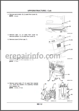
–CAB
Remove and Install Cab
Dimensions of the Cab Glass
Remove and Install Cab Glass
–COUNTERWEIGHT
Remove and Install Counterweight
–MAIN FRAME
Remove and Install Main Frame
–PUMP DEVICE
Remove and Install Pump Device
Disassemble Pump Device
Assemble Pump Device
Maintenance Standard
Disassemble Regulator
Assemble Regulator
Disassemble and Assemble Pilot Pump
–CONTROL VALVE
Remove and Install Control Valve
Disassemble Control Valve (5-Spool Section)
Assemble Control Valve (5-Spool Section)
Disassemble Control Valve (4-Spool Section)
Assemble Control Valve (4-Spool Section)
Disassemble Control Valve (Side Section)
Assemble Control Valve (Side Section)
Disassemble Housing
Assemble Housing
Disassemble Manifold
Assemble Manifold
–SWING DEVICE
Remove and Install Swing Device
Disassemble Swing Device
Assemble Swing Device
Disassemble Swing Motor
Assemble Swing Motor
Maintenance Standard
–PILOT VALVE
Remove and Install Pilot Valve
Disassemble Right and Left Pilot Valves
Assemble Right and Left Pilot Valves
Disassemble Travel Pilot Valve
Assemble Travel Pilot Valve
–PILOT SHUT-OFF VALVE
Remove and Install Pilot Shut-Off Valve
Disassemble and Assemble Pilot Shut-Off Valve
–SIGNAL CONTROL VALVE
Remove and Install Signal Control Valve
–SOLENOID VALVE
Remove and Install Solenoid Valve
Disassemble and Assemble Three-Spool Solenoid Valve
Disassemble and Assemble Swing
Preference Circuit Shift Solenoid Valve
–SHOCKLESS VALVE
Remove and Install Shockless Valve
Disassemble and Assemble Shockless Valve
-UNDERCARRIAGE
–SWING BEARING
Remove and Install Swing Bearing
Disassemble Swing Bearing
Assemble Swing Bearing
–TRAVEL DEVICE
Remove and Install Travel Device
Disassemble Travel Device
Assemble Travel Device
Disassemble Travel Motor
Assemble Travel Motor
Disassemble Brake Valve
Assemble Brake Valve
Maintenance Standard
–CENTER JOINT
Remove and Install Center Joint
Disassemble Center Joint
Assemble Center Joint
Maintenance Standard
–TRACK ADJUSTER
Remove and Install Track Adjuster
Disassemble Track Adjuster
Assemble Track Adjuster
–FRONT IDLER
Remove and Install Front Idler
Disassemble Front Idler
Assemble Front Idler
Maintenance Standard
–UPPER AND LOWER ROLLER
Remove and Install Upper Roller
Remove and Install Lower Roller
Disassemble Lower Roller
Assemble Lower Roller
Maintenance Standard
–TRACK
Remove and Install Track
Maintenance Standard
-FRONT ATTACHMENT
–FRONT ATTACHMENT
Hydraulic Circuit Pressure Release Procedure
Remove and Install Front Attachment
Remove and Install Bushing
Maintenance Standard
Standard Dimensions for
Arm and Bucket Connection
Standard Dimensions for
Arm and Boom Connection
–CYLINDER
Hydraulic Circuit Pressure Release Procedure
Remove and Install Cylinder
Disassemble Cylinder
Assemble Cylinder
Maintenance Standard
-ENGINE AND ACCESSORY
–GENERAL INFORMATION
General Repair Instruction
Illustration Arrows
Abbreviations Charts
Nut and Bolt Angular Tightening Method
Standard Bolt Torque Specifications
Recommended Thread Locking Agents
Main Data and Specification
Performance Curve
Engine External Drawing
Service Standard
Torque Specifications
Special Tools
Troubleshooting
Lubricant Application
Sealant Application
–SERVICE INFORMATION
Identification
Lubrication System
Fuel System
Cooling System
Valve Clearance Adjustment
Compression Pressure Measurement
Recommended Lubricants
Engine Oil Viscosity Chart
–ENGINE MECHANICAL
Service Precautions
General Description
Fan Center
Turbocharger
Exhaust Manifold
Inlet Manifold
Water Pump
Alternator
Oil Cooler
Injection Pump
Coupling Assembly
Cylinder Head
Rocker Arm and Shaft Assembly
Camshaft
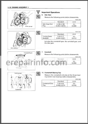
Timing Gears
Flywheel Housing
Oil Pan
Piston
Crankshaft
Crank Pulley
Flywheel
Cylinder Body
–ENGINE COOLING
Service Precautions
General Description
Water Pump
Thermostat
–ENGINE FUEL
Service Precautions
General Description
Fuel Filter
Injection Nozzle Holder
Injection Pump
–STARTING AND CHARGING
Service Precautions
Alternator
Starter Motor
–ENGINE LUBRICATION
Service Precaution
General Description
Oil Pump
Oil Coolor
–ENGINE INDUCTION
Service Precaution
Turbocharger
Disassembly
Inspection and Repair
Reassembly
What you get
You will receive PDF file with high-quality manual on your email immediately after the payment.


Reviews
There are no reviews yet.