


Factory Service Repair Manuals Set For Hitachi ZAXIS 75US Excavators. Tons of illustrations, instructions, diagrams for step by step remove and install, assembly and disassembly, service, inspection, repair, troubleshooting, tune-ups.
Format: PDF
Language: English
Bookmarks: Yes
Searchable: Yes
Wiring Diagrams: Yes
Hydraulic Diagrams: Yes
Model
Hitachi ZAXIS 75US
Contents
1.Workshop Manual
2.Technical Manual(Troubleshooting)
3.Technical Manual(Operational Principle)
1.Workshop Manual
INTRODUCTION
SAFETY
-GENERAL INFORMATION
–PRECAUTIONS FOR DISASSEMBLING AND ASSEMBLING
Precautions for Disassembling and Assembling
Maintenance Standard Terminology
–TIGHTENING TORQUE
Tightening Torque Specification
Torque Chart
Piping Joint
Periodic Replacement of Parts
–PAINTING
Painting
-UPPERSTRUCTURE
–CAB
Remove and Install Cab
Dimensions of the Cab Glass
–COUNTERWEIGHT
Remove and Install Counterweight
–MAIN FRAME
Remove and Install Main Frame
–PUMP DEVICE
Remove and Install Pump Device
Disassemble Pump Device
Assemble Pump Device
Disassemble and Assemble Valve Block
Disassemble and Assemble Control Piston
Maintenance Standard
Disassemble and Assemble Pilot Pump
–CONTROL VALVE
Remove and Install Cnntrnl Valve
Disassemble Control Valve 1
Assemble Control Valve 1
Remove and Install Control Valve 2
Disassemble Control Valve 2
Assemble Control Valve 2
–SWING DEVICE
Remove and Install Swing Device
Disassemble Swing Device
Assemble Swing Device
Disassemble Swing Motor
Assemble Swing Motor
Disassemble and Assemble Valve Block
Maintenance Standard
–PILOT VALVE
Remove and Install Right Pilot Valve
Remove and Install Left Pilot Valve
Remove and Install Travel Pilot Valve
Remove and Install Blade Pilot Valve
Disassemble Right and Left Pilot Valves
Assemble Right and Left Pilot Valves
Disassemble Travel Pilot Valve
Assemble Travel Pilot Valve
Disassemble ыaae pilot varve
Assemble Blade Pilot Valve
–PILOT SHUT-OFF VALVE
Remove and Install Pilot Shut-Off Valve
Disassemble Pilot Shut-Off Valve Assemble Pilot Shut-Off Valve
–SHOCKLESS VALVE
Remove and Install Shockless Valve
Disassemble and Assemble Shockless Valve
–SOLENOID VALVE
Remove and Install Solenoid Valve Unit
Disassemble Proportional Solenoid Valve
Assemble Proportional Solenoid Valve
Disassemble and Assemble Pilot Relief Valve
-UNDERCARRIAGE
–SWING BEARING
Remove and Install Swing Bearing
Disassemble Swing Bearing
Assemble Swing Bearing
–TRAVEL DEVICE
Remove and Install Travel Device
Disassemble Travel Device
Assemble Travel Device
Disassemble Travel Motor
Assemble Travel Motor
Disassemble Travel Brake Valve
Assemble Travel Brake Valve
Maintenance Standard
–CENTER JOINT
Remove and Install Center Joint
Disassemble Center Joint
Assemble Center Joint
Maintenance Standard
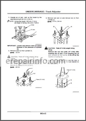
–TRACK ADJUSTER
Remove and Install Track Adjuster
Disassemble Track Adjuster
Assemble Track Adjuster
–FRONT IDLER
Remove and Install Front Idler Disassemble Front Idler
Assemble Front Idler
Maintenance Standard
–UPPER AND LOWER ROLLER
Remove and Install Upper Roller
Disassemble and Assemble Upper Roller
Remove and Install Lower Roller
Disassemble and Assemble Lower Roller
Maintenance Standard
–TRACK
Remove and Install Track
Maintenance Standard
-FRONT ATTACHMENT
–FRONT ATTACHMENT
Remove and Install Front Attachment
Maintenance Standard
Standard Dimensions for Arm and Bucket Connection
–CYLINDER
Remove and Install Cylinder
Disassemble Cylinder
Assemble Cylinder
Maintenance Standard
-ENGINE AND ACCESSORY
–GENERAL INFORMATION
General Repair Instructions
Notes on the Format of This Manual
Main Data and Specifications
Tightening Torque Specifications
–MAINTENANCE
Model Identification
Injection Pump Identification
Lubricating System
Fuel System
Cooling System
Valve Clearance Adjustment
Injection Timing
Compression Pressure Measurement
Recommended Lubricants
Engine Repair Kit
–ENGINE ASSEMBLY 1 (DISASSEMBLY)
General Description
Disassembly
–ENGINE ASSEMBLY 2 (INSPECTION AND REPAIR)
Inspection and Repair
–ENGINE ASSEMBLY 3 (REASSEMBLY)
Reassembly
–LUBRICATING SYSTEM
Main Data and Specification
General Description
Oil Pump
Oil Filter with Built-in Oil Cooler
–COOLING SYSTEM
Main Data and Specification
General Description
Thermostat
–FUEL SYSTEM
Main Data and Specification
General Description
Injection Nozzle
Injection Pump Calibration Data
–ENGINE ELECTRICALS
Starter
Alternator
–TROUBLESHOOTING
Hard Starting
Unstable Idling
Insufficient Power
Excessive Fuel Consumption
Excessive Oil Consumption
Overheating
White Exhaust Smoke
Darkish Exhaust Smoke
Oil Pressure does not Rise
Abnormal Engine Noise
–SPECIAL TOOL LIST
Special Tool List
–REPAIR STANDARDS
General Ruler
Repair Standard Chart
–CONVERSION TABLE
Length
Area
Volume
Mass
Pressure
Torque
Temperature
2.Technical Manual(Troubleshooting)
-OPERATIONAL PERFORMANCE TEST
–INTRODUCTION
Operational Performance Tests
Preparation for Performance Tests
–ENGINE TEST
Engine Speed
Engine Compression Pressure
Valve Clearance Adjustment
Nozzle Check
Injection Timing
–EXCAVATOR TEST
Travel Speed
Track Revolution Speed
Mistrack Check
Travel Parking Function Check
Swing Speed
Swing Function Drift Check
Swing Motor Leakage
Swing Bearing Piay
Maximum Swingable Slant Angle
Hydraulic Cylinder Cycle Time
Dig Function Drift Check
Control Lever Operating Force Control Lever Stroke
Combined Boom Raise/Swing Function Check
–COMPONENT TEST
Primary Pilot Pressure
Secondary Pilot Pressure
Solenoid Valve Set Pressure
Main Pump Delivery Pressure
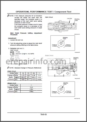
Main Relief Valve Set Pressure
Overload Relief Valve Set Pressure
Main Pump Flow Rate Measurement
Swing Motor Drainage
Travel Motor Drainage
–STANDARD
Operational Performance Standard Table
Main Pump P-Q Diagram
Injection Pump
Dr EX Monitor Indicating Values
-TROUBLESHOOTING
–GENERAL
Introduction
Diagnosing Procedure
Built-in Diagnosing System Operation
Built-In Diagnosing Function Display List Dr EX Operation
Dr EX Fault Code List
Dr EX Monitoring Item List
Dr EX Special Function
Dr EX Service Mode
Adjustment Data List
–COMPONENT LAYOUT
Mam Components
Electrical Component (Overall System)
Electrical System (Monitors and Switches)
Control Valve
Others
–TROUBLESHOOTING A
Troubleshooting A Procedure
Fault Code List
Fault Code 01, 02, 03
Fault Code 04
Fault Code 06
Fault Code 07
Fault Code 10
Fault Code 16, 18
Sensor Activating Range
–TROUBLESHOOTING B
Troubleshooting B Procedure
Relationship between Machine Trouble Symptoms and Related Parts
Correlation between Trouble Symptoms and Part Failures
Engine System Troubleshooting
All Actuator System Troubleshooting
Front Attachment System Troubleshooting
Swing System Troubleshooting
Travel System Troubleshooting
Blade System Troubleshooting
Other System Troubleshooting
Engine Speed Adjustment and Engine Learning
Exchange Inspection
Emergency Boom Lowering Procedure
–TROUBLESHOOTING C
Troubleshooting C Procedure
Malfunction of Coolant Temperature Gauge
Malfunction of Fuel Gauge
Malfunction of Indicator Light Check System
Malfunction of Alternator Indicator
Malfunction of Engine Oil Pressure Indicator
Malfunction of Overheat Indicator
Malfunction of Air Filter Restriction Indicator
Malfunction of Buzzer
Malfunction of LCD
Malfunction of Hour Meter
Malfunction of Hydraulic Oil Filter Indicator (Optional)
–ELECTRICAL SYSTEM INSPECTION
Precautions for Inspection and Maintenance
Instructions for Disconnecting Connectors
Fuse Inspection
Fusible Link Inspection
Battery Voltage Check
How to Troubleshoot Alternator Malfunctions
Continuity Check
Voltage and Current Measurement Check by False Signal
Test Harness
–ICX
Outline
ICX Fault Code List
Satellite Terminal Fault Code List
Fault Code 1 to 6
Fault Code 7 to 10
Some Parts of Data in Daily Report, Frequency Distribution, Cumulative Operation Hours are not Recorded
Troubleshooting and Setting of ICX and Satellite Terminal Using Dr EX
Satellite Communication System
3.Technical Manual(Operational Principle)
-GENERAL
–SPECIFICATION
Specifications
Working Ranges and Machine Transportation Dimensions
–COMPONENT LAYOUT
Mam Components
Electrical System (Overall System)
Electrical System (Monitor and Switches)
Others
–COMPONENT SPECIFICATIONS
Engine
Engine Accessories
Hydraulic Component
Filter
Electrical Component
-SYSTEM
–CONTROL SYSTEM
Outline
Engine Control
Pump Control
Valve Control
Arm Flow Combining Control
Other Controls
–HYDRAULIC SYSTEM
Outline
Pilot Circuit
Main Circuit
–ELECTRICAL SYSTEM
Outline
Main Circuit
Electric Power Circuit (Key Switch OFF) Indicator Light Check Circuit (Key Switch: ON)
Accessory Circuit
Preheat Circuit (Key Switch: Heat)
Starting Circuit (Key Switch: Start)
Charging Circuit (Key Switch: ON)
Serge Voltage Prevention Circuit
Engine Stop Circuit
-COMPONENT OPERATION
–PUMP DEVICE
Outline
Mam Pumps (1 and 2)
Main Pump 3 and Pilot Pump
–SWING DEVICE
Outline
Swing Motor
Valve Unit
Swing Reduction Gear
–CONTROL VALVE
Outline
Hydraulic Circuit
Flow Combiner Valve
Main Relief Set Pressure Change Boom Anti-Drift Valve
Main Relief Valve
Overload Relief Valve
–PILOT VALVE
Outline
Operation
–TRAVEL DEVICE
Outline
Travel Motor
Parking Brake
Travel Brake Valve
Travel Reduction Gear
–OTHERS (UPPERSTRUCTURE)
Pilot Shut-Off Valve
Shockless Valve
Solenoid Valve Unit
EC Motor
–OTHERS (UNDERCARRIAGE)
Swing Bearing
Center Joint
Track Adjuster
What you get
You will receive PDF file with high-quality manual on your email immediately after the payment.


Reviews
There are no reviews yet.