


Factory Service Manual For JCB Telescopic Handler. Manual Contains Illustrations, Instructions, Diagrams For Step By Step Remove And Install, Assembly And Disassembly, Service, Inspection, Repair, Troubleshooting, Tune-Ups.
Format: PDF
Language: English
Pages: 736
Number: 9803/3600
Searchable: Yes
Wiring Diagrams: Yes
Hydraulic Diagrams: Yes
Model
JCB Telescopic Handler
525-58
525-58 Farm Special
525-67
525-67 Farm Special
Serial No. from 561001
525-58
525-67 Farm Special Plus
525-67 Basic Servo Options
527-58
527-67
Serial No. from 572775
530-95
Serial No. from 564980
530-110
Serial No. from 563359
530-110
530-120
PlaceAce
530-110
530-120
Servo Options
530-120
Serial No. from 562601
530-67
530-67 Farm Special
Serial No. from 571001
535-67
Serial No. from 572775
537-120
537-130
Serial No. from 572900
Contents
-GENERAL
Fluids, Lubricants, Capacities & Specifications
Service Schedules
Greasing
Oiling
Boom Safety Strut
-HYDRAULICS
Technical Data
General Description
Hydraulic Fluid Level & Filter
Draining Fluid & Cleaning Suction Strainers
Hydraulic Tank Removal & Replacement
Pump Operation
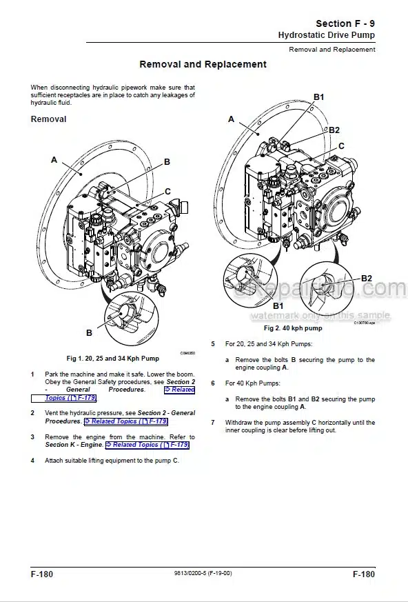
Pump Removal & Replacement
Pump Dismantle & Assembly
Supplementary Pump
Neutral Circuits
Boom
Stabiliser
M.R.V. Operation
A.R.V. Operation
Control Valve Block
Pressure Testing
Lift Rams Removal & Replacement
Displacement Rams Removal & Replacement
Extension Ram Removal & Replacement
Boom Hoses
Fan Motor
Schematic Hydraulic Circuit
-BODY AND FRAMEWORK
Boom Cab
Front Windscreen
Window
Fuel Tank
Air Conditioning
-PLACEACE CONTROL SYSTEM
Technical Data
Control System Description
Valve Block Operation
Pulsar Description & Operation
Valve Block Removal & Replacement
Pulsar Solenoid Removal & Replacement
Main Spool Removal & Replacement
Boom Angle Sensor Removal & Replacement
Boom Extension Sensor Removal & Replacement
Attitude Sensor Removal & Replacement
Driver Cards Removal & Replacement
Display Unit Removal & Replacement
Joystick Removal & Replacement
Lever Control (Stabilisers) Removal & Replacement
Control Valve Dismantle & Assembly
Valve Stack Dismantle & Assembly
Pressure Testing
Full System Calibration
Pulsar Solenoid Calibration
Driver Card Calibration/Adjustment
Fault Finding
Schematic Hydraulic Circuit
Schematic Electrical Circuit
-SERVO CONTROL SYSTEM
Technical Data
Description
Valve Block
Joystick
Cab And Chassis
Pressure Testing
Fault Finding
-ENGINE
Technical Data
General Description
Engine Cover
Engine Oil Filter
Fuel Filter
Fuel Pump
Bleeding
Cooling System
Alternator Drive Belt
Pre-Cleaner
Air Filter
Radiator
Engine Removal & Replacement
Exhauster Removal & Replacement
Turbo Charger Engine Insulation
Naturally Aspirated Engine Insulation
-TRANSMISSION
Syncro Shuttle Technical Data
Syncro Shuttle General Description
Powershift Technical Data
Recovery Procedure
Checking & Changing Oil
Syncro Shuttle General Description & Operation
Syncro Shuttle Operation
Syncromesh Description
Four Wheel Drive Clutch Operation
Powershift General Description
Powershift Operation
Powershift Drive Paths
Syncro Shuttle Fault Finding
Powershift Fault Finding
Transmission Removal & Replacement
Torque Converter Removal & Replacement
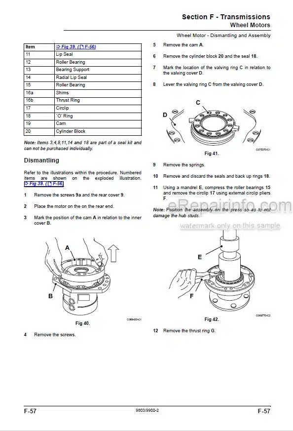
Syncro Shuttle Dismantling
Syncro Shuttle Assembly
Solenoid Valve Dismantling & Assembly
Reverser Unit Dismantling
Reverser Unit Assembly
Reverser Unit (Later Type) Assembly
-AXLES
Technical Data
Road Wheel Removal & Replacement
Front Axle Breather Removal & Replacement
Axle Oil Level
Cutaway of Front Axle
Cutaway of Rear Axle
Front Axle (Fixed)
Rear Axle
Brakes Dismantling
Brakes Assembly
Front Drive Head Dismantling
Front Drive Head Assembly
Renewing Axle Pinion Oil Seal
Rear Drive Head Dismantling
Rear Drive Head Assembly
Limited Slip Differential Dismantle & Assembly
-BRAKES
Technical Data
Parking Brake
Brake System
-HYDRAULIC STEERING
Technical Data
General Description
Flow Regulating Valve Operation
Tandem Steering/Fan Pump Dismantling & Assembly
Steering/Fan Pump Removal & Replacement
Single Steering/Fan Pump Dismantling & Assembly
System Operation (Machines Without IP67 Electrics)
Steering Description
Steering Shock Valve Description
Priority Valve Description
Steering Unit Removal & Replacement
Steering Unit Dismantling & Assembly
Steering Mode Valve Removal & Replacement
Steering Mode Valve Dismantling & Assembly
Steering Ram Removal & Replacement
Steering Ram Dismantling & Assembly
Bleeding
Pressure Testing
-ELECTRICS
Introduction
Technical Data
Fuses
Relay Location
Test Methods
Batteries Testing
Alternator
Starting Circuit Test
Starter Motor
Safe Load Indicator Adjustment
Harness Repair
Wiring Diagram
-SERVICE TOOLS
Numerical List
Section List
Sealing and Retaining Compounds
What you get
You will receive PDF file with high-quality manual on your email immediately after the payment.


Reviews
There are no reviews yet