


Factory Service Manual For Komatsu Hydraulic Excavator. Manual Contains Illustrations, Instructions, Diagrams For Step By Step Remove And Install, Assembly And Disassembly, Service, Inspection, Repair, Troubleshooting, Tune-Ups.
Format: PDF
Language: English
Pages: 636
Issued: march 2003
Searchable: Yes
Model
Komatsu Hydraulic Excavator
PC5500-6 Diesel
SN 15017 And Up
Contents
SAFETY – FOREWORD
TECHNICAL DATA (LEAFLET)
ASSEMBLY PROC EDURE (BROCHURE)
-MAIN ASSEMBLY GROUPS
General Lay Out
-DRIVE
Engine And PTO Mounts
Coupling
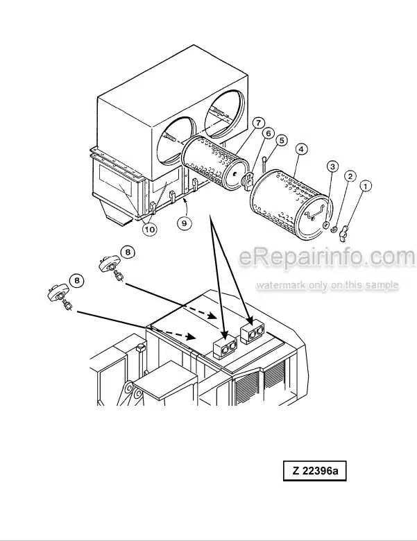
Air Filter
Fan Drive And Radiator Assembly
Radiator Fan Drive Speed Adjustment
Pump Distributor Gearbox (PTO)
Pump-Spline Lubrication
PTO Lubrication And Cooling
Hydraulic Pumps – Location, Drive Speed And Flow Rates
-HYDRAULIC OIL TANK
Main Oil Tank, Location Of Switches, Sensors Etc.
Suction Oil Tank With Strainers
Return Oil Collector Tube With Strainer
Back Pressure Valve
Return And Leak Oil Filter
Breather Filter
-HYDRAULIC OIL COOLING
General
Function Of The Hydraulic Oil Cooling Circuit
Adjustment Of The Back Pressure Valve
Fan Drive (Two Stage Cooler Fan Rpm Control)
Pressure Relief Valves And Solenoid Valve
Fixed Displacement Pump, With Variable Setting
Radiator Fan Drive Speed Adjustment
-CONTROLLING
Control And Filter Panel Location Of Components (Valves, Switches, Sensors Etc.)
Pilot Pressure Supply And Adjustments
Remote Control Valves Arrangement
Function Principle Of The
Electro-Hydraulic- Proportional Control
Potentiometer Control (Lever. Joy Stick)
Potentiometer Control (Pedal)
Proportional Amplifier Module. Type A (For Swing Brake Only)
Proportional Amplifier Module. Type B (For Boom. Stick. Bucket. Swing And Travel)
Ramp Time Module (Analogue Command Value Module For Boom. Stick.
Travel And Swing Function)
Adjustments Of Amplifier Modules (General)
Adjusting The Amplifiers Type B
Adjusting The Amplifiers Type A
Adjusting The Ramp Time Module
-COMPONENTS-HYDRAULIC
Main Control Blocks And High Pressure Filter FSA
Main Control Blocks And High Pressure Filter BHA
Distributor Manifold – Restrictor Blocks FSA
Distributor Manifold – Restrictor Blocks BHA
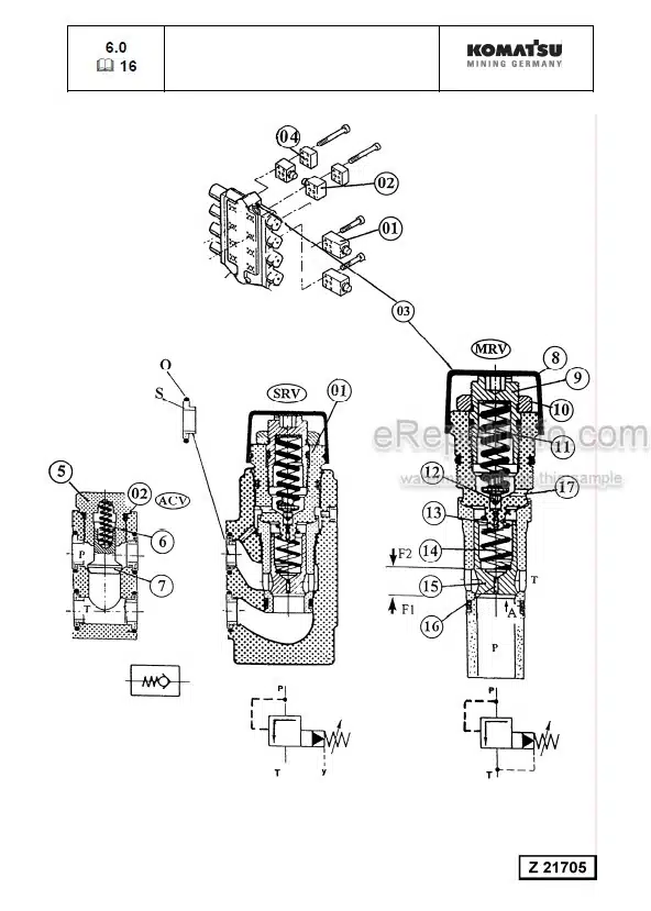
Restrictor Block With Pressure Relief Valve
Anti Cavitation Valve Block
Remote Control Valves
Directional Solenoid Valves (4 Way / 3 Positions)
Proportional Solenoid Valves
High Pressure Filter
Control Blocks And Valves
Load Holding Valve
Travel Brake Valve
Pressure Reducing Valve
Directional Solenoid Valves (2 Positions / 4-Ways)
Pressure Increasing Valve
-MAIN HYDRAULIC PUMPS AND PUMP REGULATION
Main Pumps
Electronic Pump Regulation System
Hydraulic Constant Regulation System
Determination of the Peak Point
Engine Speed Sensor (Pick Up)
-OPERATING HYDRAULIC
Hydraulic For The Attachment Cylinder FSA And BHA
Hydraulic For The Swing Circuit
Hydraulic For The Travel Circuit
-HYDRAULIC TRACK TENSIONING SYSTEM
Functional Description
Pressure Increasing Valve
Tensioning Cylinder
Adjustments / Checks
Functional Test
-HYDRAULIC OPERATED ACCESS LADDER
General
Function Of Hydraulic Operated Access Ladder
-CENTRAL REFILLING SYSTEM
General
Function
-HINTS FOR THE HYDRAULIC CIRCUIT DIAGRAM
Symbols
-HINTS FOR THE ELECTRIC CIRCUIT DIAGRAM
Designation Of Electrical Devices
Symbols
General Information
Reading A Circuit Diagram
-ECS
General Design of the ECS-T System
How to Proceed due Maintenance and Installation
Front Connector Arrangement
Power Supply
Function Explanations With Electro Diagram
Hints For Reading The Functional Flow Charts
-APPENDIX
Check List Valve Logic
Diagnose Code MC7
What you get
You will receive PDF file with high-quality manual on your email immediately after the payment.


Reviews
There are no reviews yet.