


Factory Repair Manual For Manitou Telehandler. Manual Contains Illustrations, Instructions, Diagrams For Step By Step Remove And Install, Assembly And Disassembly, Service, Inspection, Repair, Troubleshooting, Tune-Ups.
Format: PDF
Language: English
Pages: 553
Number: 648001
Wiring Diagrams
Hydraulic Diagrams
Model
Manitou Telehandler
MVT1230L Comfort Line
Contents
SPECIFICATION
OILS – GREASES – FLUIDS – FUEL – FILTERS
SCHEDULED MAINTENANCE
ELECTRICAL SYSTEM
HYDRAULIC MANEUVERING SYSTEM
HYDRAULIC STEERING – BRAKE SYSTEM
TRANSMISSION HYDRAULIC SYSTEM
-HYDRAULICS
Pressure Testing
Safety Valve
Removing The Suction Screen And Return
Faults, Causes, Cures
TRANSMISSION INSPECTION AND ADJUSTMENTS
-BRAKE SYSTEM
Draining Procedure
Parking Brake
-THE DISASSEMBLY AND ASSEMBLY OF THE BOOMS RECOMMENDATIONS
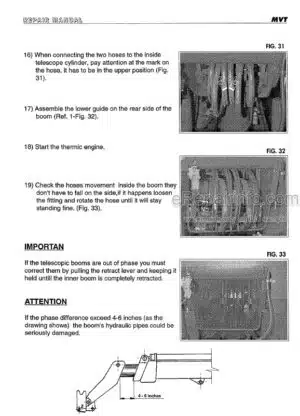
Boom Hose Replacement
Removal Of Tilting Cylinder
Removal Of The Cylinder From The Small Telescope
Removal Of The Small Telescope
Removal Of The Intermediate Telescope Cylinder
Removal Of Intermediate Telescope
REMOVING THE TELESCOPIC BOOM
REMOVING THE LIFTING CYLINDER
REMOVING THE COMPENSATION CYLINDERS
LIFTING CYLINDER DISMANTLING
TILTING CYLINDER DISMANTLING
1° TELESCOPE CYLINDER DISMANTLING
2° TELESCOPE CYLINDER DISMANTLING
COMPENSATING CYLINDER DISMANTLING
LEVELING CYLINDER DISMANTLING
ENGINE DISMANTLING
REMOVING THE WHEELS
-REMOVING THE FRONT AND REAR DIFFERENTIAL AXLE
Removing The Front Differential Axle And Hydrostatic Motor
Removing The Hydrostatic Motor Only
Removing The Rear Differential Axle
REMOVING THE WATER AND OIL RADIATOR
REMOVING THE CONTROL VALVE
REMOVING THE CAB
DISMANTLING FRONT AXLE
DISMANTLING REAR AXLE
-MAINTENANCE AND REPAIR INSTRUCTION AXLES 279
Introduction
Maintenance And Lubrication
Brakes
Brakes/External Adjustment
Safety Brake
Planetary 4,25-5,25
Planetary Wheel Hub 4,25-5,25
Epycicloidal Reduction 4,25-5,25
Articulation 272 – 277 – 279 (Disassembly)
Assembling Articulation 272 – 277 – 279
Articulation 272 – 277 – 279 (Assembly)
Steering Cylinder 277 – 279
Steering Cylinder Assembly 277 – 279
Bevel Pinion Support
Axle Bevel Pinion Support 277 – 279
Taper Roller Bearings Of Differential
Disassembly Of Differential
Assembly Of The Differential
Conversion Tables
Tightening Torques
Trouble Shooting
Special Tools
MAINTENANCE AND REPAIR INSTRUCTION GEARBOX 353
-PUMP A4VG40-56 REPAIR
Sectional View
Seal Kits And Sub-Assemblies
Sealing Of (He Drive Shaft
Check Throttle
Sealing Of Boost Pump
Sealing Of The Control Piston Cover
Sealing Of Valves
Sealing Of The Pressure Cut-Off Valve
Sealing Of The Regulator Valve
Disassembly Of The Control Module
Control Module
Disassembly Of The Pump
Removing The Rotary Group
Disassembly Of The Positioning Piston
Inspection Notes
Inspection Of The Rotary Group Parts
Installing The Rotary Group
-PERKINS NEW 1000 SERIES WORKSHOP MANUAL
General Information
Specifications
Cylinder Head Assembly
Piston And Connecting Rod Assemblies
Crankshaft Assembly
Timing Case And Drive Assembly
Cylinder Block Assembly
Engine Timing
Aspiration System
Lubrication System
Fuel System
Cooling System
Flywheel And Housing
Electrical Equipment
Auxiliary Equipment
List Of Special Tools
What you get
You will receive PDF file with high-quality manual on your email immediately after the payment.


Reviews
There are no reviews yet.