


Factory Service And Maintenance Manual For Manitowoc Crane. Manual Contains Important Information And Instructions For Maintenance Description Of The Functions And Capabilities Of The System. Illustrations, Instructions, Diagrams For Step By Step Remove And Install, Assembly And Disassembly, Service, Inspection, Repair, Troubleshooting, Tune-Ups.
Format: PDF
Language: English
Pages: 376
Number: CTRL229-09 (september 2016)
Bookmarks: Yes
Searchable: Yes
Wiring Diagrams: Yes
Hydraulic Diagrams: Yes
Model
Manitowoc Crane
MLC650
SN XXXXXRef
Contents
-INTRODUCTION
Continuous Innovation
Safety Messages
Safe Maintenance Practices
Protection of the Environment
Identification and Location of Major Components
-HYDRAULIC SYSTEM
Hydraulic System Overview
Hydraulic Pump Identification
Hydraulic Motor Identification
Manifold Identification
Hydraulic System Specifications
Hydraulic System Maintenance
Shop Procedures
Initial Hydraulic System Startup
-ELECTRICAL SYSTEM
Electrical Drawings and Schematics
Electrical Power Sequence
Circuit Breakers. Fuses, and Relays
Inspect Electrical Components
CAN Bus Control System
-BOOM
General Maintenance
Boom and Luffing Jib Angle Indicator Calibration
Boom Stop Limit Switch
Physical Boom Stop
Boom and Luffing Jib Angle Indicators
Mast Angle Sending Unit
Fleeting Sheave Maintenance
Boom Top Electrical Schematic
Luffing Jib Top Electrical Schematic
Boom Wind Cap Electrical Schematic
Strap Inspection and Maintenance
Lattice Section Inspection and Lacing Replacement
-HOISTS
Drum 1 Main Hoist
Drum 2 Main Hoist
Drum 3 Whip Hoist
Drum 4 Boom Hoist or Mast Hoist (VPC-MAX)
Drum 5 Boom Hoist (VPC-MAX)
Drum 6 Luffing Hoist
Gearboxes
Drum Motor Speed Sensor
Block Level
Block-Up Limit Switch
Pressure Roller
Wire Rope Inspection and Replacement
Sheave, Roller, and Drum Inspection
Load Block and Hook-and-Weight Ball Inspection
-SWING SYSTEM
General
Swing System Overview
Swing Brake Operation
Swing Operation
Swing Drive System
Planetary Swing Drive Gear Oil
Manual Release of Swing Brake
Swing Motor Speed Sensor
-POWER TRAIN
Batteries
Battery Disconnect Switch
Engine Controls
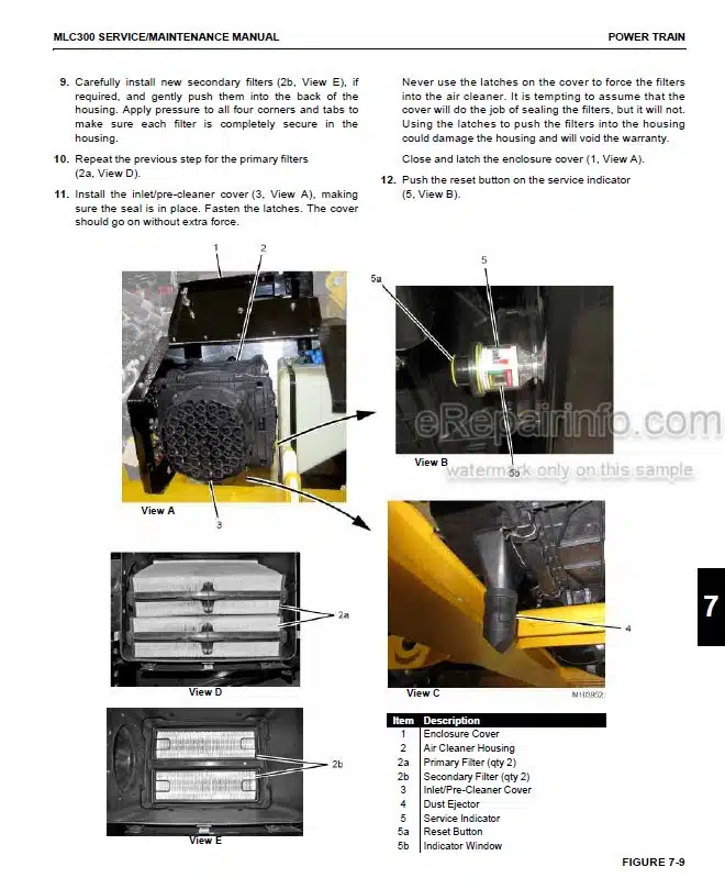
Air Cleaner—Tier 4
Air Cleaner—Tier 3
Engine Throttle Adjustment
Engine Electrical Schematic
Tier 4 ECM Electrical Schematic— Power and Ground Circuits
Tier 3 ECM Electrical Schematic— Power and Ground Circuits
Engine Enclosure
Engine Belt Routing
Engine Radiator
Diesel Particulate Filter
-UNDERCARRIAGE
General
Hydraulic Travel System
Turntable Bearing Alignment
Turntable Bearing Bolt Periodic Tightening
Replacing Turntable Bolts
Crawler Preventive Maintenance
Carbody Jack Cylinders and Carbody/Crawler Pin Pullers
Carbody Jack Cylinders Control
Crawler/Carbody Pin Pullers Control
Crawler Tread Slack Measurement
Crawler Tread Slack Adjustment
Crawler Tensioning Assembly and Hydraulic Hand Pump
-LUBRICATION
Lubrication
-ACCESSORIES
Adapter Frame-to-Rotating Bed Pin Pullers
Rotating Bed Jack Cylinders
Rotating Bed Jack Stowage Cylinder
Rigging Winch (Drum 0)
Mast Assist Cylinders
Self-Assembly Cylinder (Optional)
Cab Tilt
VPC and VPC-MAX Systems
Active Fixed Mast Stop System
What you get
You will receive PDF file with high-quality manual on your email immediately after the payment.


Reviews
There are no reviews yet.