


Factory Service Repair Manual For Massey Ferguson 9695 9795 Rotary Combine. Tons of illustrations, instructions, diagrams for step by step remove and install, assembly and disassembly, service, inspection, repair, troubleshooting, tune-ups.
Format: PDF
Language: English
Bookmarks: Yes
Searchable: Yes
Number: 4283358M1
Wiring Diagrams: Yes
Hydraulic Diagrams: Yes
Model
Massey Ferguson 9695, 9795
Contents
- -GENERAL INFORMATION
–SAFETY
Safety Alert Symbol
Signal Words
Shields and Latches
Header Lift Cylinder Stop
Rear Hook
Travel On Public Roads
–GENERAL INFORMATION
Machine Main Components
How A Combine Works
Cutting and Feeding
Threshing and Separating
Cleaning
Combine Identification
Machine Serial Number
Engine Serial Number
Fuel Injection Pump Dataplate5
ECM Dataplate5
Transmission Serial Number5
Final Drive Serial Number
Headers
Lubrication and Maintenance
Lubricants
Service Procedures
Service Periods
Lubrication and Maintenance
Lubrication Details
Front of Combine
Lefthand Side
Righthand Side
Rear Axle
Auto Lube
Auto Lube Intervals
Auto Lube Diagnosis
Engine
Type of Engine Oil
Viscosity
Oil Additives
Checking Oil Level
Changing Engine Oil and Filters
Rotor Gearbox
Transmission
Checking and Changing Lubricant
Brakes
Master Cylinder Oil Reservoir
Bleeding Brake System
Final Drive
Tires and Wheels
Tire Pressure
Dual Tires
Maintenance of Tires
Removing Wheel from Combine
Wheel Installation
Tire Dimensions
Drive Belts
Banded Drive Belt
Maintenance of Belts
Belt Changing Guides
Belt Sheave Alignment
Belt Run In Procedure
Belt Troubleshooting
Belt Problem and Wear Guide
Roller Chains
Inspection of Drive Chains and Sprockets
Drive Chain Adjustment and Tightening
Drive Chain Sprocket and Idler Alignment
Drive Chain Elongation and Sprocket Wear
Normal Tooth Wear
Not Normal Tooth Wear
Worn Chain on New Sprockets
Drive Chain Service Tips
Chain Replacement
Cleaning and Lubricating Chains
Drive Chain Lubrication
Drive Chain Lubricants
Good Drive Chain Lubrication
Roller Chain Drive Troubleshooting Guide
Speed of Components
Drives Listing and Specifications
Drives Speeds And Specifications
Engine Platform
Engine Platform Ladder
Engine Compartment
Fuel System
Fuel Handling
Fuel Vent Breather
Fuel Filter/Water Separator
Bleeding the Fuel System
Engine Cooling System
Coolant System Monitoring
Monitor Warnings
AntiFreeze Type
Coolant Change Period
Engine Cooling System Coolant
Checking Coolant Level
Radiator
Thermostat
Draining System
Filling System
Engine Air Cleaner
Outer Filter Element
Inner Filter Element
Hydraulics
Checking Oil Level
Hydraulic Oil Filter
Changing Hydraulic Oil
Removing Air From Hydraulic System
Hydraulic Pump
Steering Priority Valve
Main Hydraulic Control Valve
Unloader Auger Engagement Valve
Pump Drive Disconnect Valve
Accumulator
Hydrostatic Drives – A66
Hydrostatic Drives – A76
Hydraulic Oil Cooler
Rotor Speed Control
Air Conditioning System
Compressor
Condenser
Receiver-Drier
Cab Filters
Cab Filter – Primary
Cab Filter – Secondary
Recirculation Filter
Air Filter Cleaning Procedure
Windshield Washer Reservoir
Cleaning Windshield
Storage Preparation
Combine
Engine
Preparation For Use After Storage
Combine
Engine
Torque Charts
Standard Torque Specifications
Metric Capscrew Markings and Torque Values
Metric Conversions
Fractions, Decimals, and Millimeters Conversion Chart
Decimal Equivalents of 8ths, 16ths, 32nds, and 64ths
Decimal Equivalents Of Letter Size Drills
Decimal Equivalents of Number Size Drills
Tap Drill Sizes – SAE & Metric
American Standard Pipe Thread and Tap Drill Sizes
Electrical Formulas
Amperes (Current Flow)
Volts (Electromotive Force)
Ohms (Resistance)
Watts
Horsepower
Belt Speed Calculation Formulas
Geometrical Formulas
Circumference of a Circle
Area of a Circle
Volume of a Cylinder
Volume of a Sphere
Area of a Triangle
Metric to Imperial and Imperial to Metric Conversion Factors
Measures of Temperature
Measures of Power
Measures of Pressure
Measures of Length
Measures of Area
Measures of Volume (Dry)
Measures of Volume (Liquid)
Measures of Mass (Weight)
Measures of Effort (Torque)
Reference Tables - -SPECIFICATIONS
General Lubrication – A66/9695/660B
Combine – A66/9695/660B
General – A66/9695/660B
Main Body – A66/9695/660B
Feeder – A66/9695/660B
Front Beater – A66/9695/660B
Stone Trap – A66/9695/660B
Thresher-Separator – A66/9695/660B
Rotor – A66/9695/660B
Feeder Reverser – A66/9695/660B
Concave – A66/9695/660B
Concave Overlap – A66/9695/660B
Separator Area – A66/9695/660B
Separator Return Pan – A66/9695/660B
Cascade Chaffer Pan – A66/9695/660B
Cleaning Fan – A66/9695/660B
Shoe – A66/9695/660B
Chaffer – A66/9695/660B
Sieve – A66/9695/660B
Cleaning Area – A66/9695/660B
Elevators (Clean Grain And Return) – A66/9695/660B
Grain Tank – A66/9695/660B
Steering Axle – A66/9695/660B
Ground Drive – A66/9695/660B
Transmission – A66/9695/660B
Final Drive – A66/9695/660B
Brakes – A66/9695/660B
Wheel Bolt Torque – A66/9695/660B
Front Wheels
Rear Wheels
Crop Residue Disposal System – A66/9695/660B
Straw Chopper – A66/9695/660B
Straw Spreader – A66/9695/660B
Chaff Spreader – A66/9695/660B
Weights – A66/9695/660B
Capacities – A66/9695/660B
Engine – A66/9695/660B
Electrical System – A66/9695/660B
Batteries – Maintenance-Free – A66/9695/660B
Operator’S Cab – A66/9695/660B
Cab – A66/9695/660B
Air Conditioning – A66/9695/660B
Mirrors – A66/9695/660B
Lighting – A66/9695/660B
Machine Monitor – A66/9695/660B
Grain Loss Monitor – A66/9695/660B
Digital Display – A66/9695/660B
Hydraulic System – A66/9695/660B
Hydrostatic Rotor And Propulsion Drive – A66/9695/660B
Hydraulic Pressures – A66/9695/660B
Filters – A66/9695/660B
Hydraulic Pump – A66/9695/660B
Hydraulic Control Valves – A66/9695/660B
Unloader Swing In And Out Valve – A66/9695/660B
Auger Swing Check Valves – A66/9695/660B
Header Lift / Lower And Feeder Reverser Valve – A66/9695/660B
Reel Fore And Aft Valve (Ce Only) – A66/9695/660B
Chaff Spreader, Reel Lift / Lower, And Master Valve – A66/9695/660B
Reel Lift Raise Valve – A66/9695/660B
Reel Speed Valve – A66/9695/660B
Reel Speed Pressure Compensator – A66/9695/660B
Header Lowering Valve- A66/9695/660B
Chaff Spreader / Rotary Screen Pressure Compensator – A66/9695/660B
Pressure Compensated, Flow Regulator – A66/9695/660B
Chaff Spreader, Rotary Screen, Header Lift Load Sense, And Reel Speed Check Valves – A66/9695/660B
Reel Fore And Aft Check Valves (Ce Only) – A66/9695/660B
Header Lift And Feed Reverser Check Valves – A66/9695/660B
Unloader Swing Fast Valve
Header Lift Cylinder – A66/9695/660B
Accumulator – A66/9695/660B
Unloading Auger Tube Swing Cylinder -A66/9695/660B
Unloader Auger Engage Cylinder – A66/9695/660B
Unloader Auger Engage Valve – A66/9695/660B
Power Steering Cylinder – Standard Adjustable Axle – A66/9695/660B
Power Steering Cylinder – Rear Wheel Assist – A66/9695/660B
Steering Control Unit – A66/9695/660B
Rear Wheel Assist Motor – A66/9695/660B
Powered Rear Valve Assembly – A66/9695/660B
Steering Priority Valve Assembly – A66/9695/660B
Shuttle Valve – A66/9695/660B
Hydrostatic Rotor Drive – A66/9695/660B
Hydrostatic Propulsion Drive – A66/9695/660B
Hydraulic Rotary Screen Drive – A66/9695/660B
Feed Reverser Hydraulic Motor And Clutch Assembly – A66/9695/660B
Oil Cooler Bypass Check Valve -A66/9695/660B
Lateral Tilt Valve – A66/9695/660B
Lateral Tilt Cylinder – A66/9695/660B
Chaff Spreader Motors – A66/9695/660B
Variable Speed Header Drive Sheave Relief Valve – A66/9695/660B
General Lubrication – A76/9795/670B
Combine – A76/9795/670B
General – A76/9795/670B
Main Body – A76/9795/670B
Feeder – A76/9795/670B
Front Beater – A76/9795/670B
Stone Trap – A76/9795/670B
Thresher-Separator – A76/9795/670B
Feeder Reverser – A76/9795/670B
Rotor – A76/9795/670B
Concave – A76/9795/670B
Concave Overlap – A76/9795/670B
Separator Area – A76/9795/670B
Separator Return Pan – A76/9795/670B
Cascade Chaffer Pan – A76/9795/670B
Cleaning Fan – A76/9795/670B
Shoe – A76/9795/670B
Chaffer – A76/9795/670B
Sieve – A76/9795/670B
Cleaning Area – A76/9795/670B
Elevators (Clean Grain And Return) – A76/9795/670B
Grain Tank – A76/9795/670B
Steering Axle – A76/9795/670B
Ground Drive – A76/9795/670B
Transmission – A76/9795/670B
Final Drive – A76/9795/670B
Brakes – A76/9795/670B
Wheel Bolt Torque – A76/9795/670B
Front Wheels
Rear Wheels
Crop Residue Disposal System – A76/9795/670B
Straw Chopper – A76/9795/670B
Straw Spreader – A76/9795/670B
Chaff Spreader – A76/9795/670B
Weights – A76/9795/670B
Capacities – A76/9795/670B
Engine – A76/9795/670B
Electrical System – A76/9795/670B
Batteries – Maintenance-Free – A76/9795/670B
Operator’S Cab – A76/9795/670B
Cab – A76/9795/670B
Air Conditioning – A76/9795/670B
Mirrors – A76/9795/670B
Lighting – A76/9795/670B
Machine Monitor – A76/9795/670B
Grain Loss Monitor – A76/9795/670B
Digital Display – A76/9795/670B
Hydraulic System – A76/9795/670B
Hydrostatic Rotor And Propulsion Drive – A76/9795/670B
Hydraulic Pressures – A76/9795/670B
Filters – A76/9795/670B
Hydraulic Pump – A76/9795/670B
Hydraulic Control Valves – A76/9795/670B
Unloader Swing In And Out Valve – A76/9795/670B
Auger Swing Check Valves – A76/9795/670B
Header Lift / Lower And Feeder Reverser Valve – A76/9795/670B
Reel Fore And Aft Valve (Ce Only) – A76/9795/670B
Chaff Spreader, Reel Lift / Lower, And Master Valve – A76/9795/670B
Reel Lift Raise Valve – A76/9795/670B
Reel Speed Valve – A76/9795/670B
Reel Speed Pressure Compensator – A76/9795/670B
Header Lower Valve
Chaff Spreader / Rotary Screen Pressure Compensator – A76/9795/670B
Pressure Compensated, Flow Regulator – A76/9795/670B
Chaff Spreader, Rotary Screen, Header Lift Load Sense, And Reel Speed Check Valves – A76/9795/670B
02-92
Reel Fore And Aft Check Valves (Ce Only) – A76/9795/670B
Header Lift And Feed Reverser Check Valves – A76/9795/670B
Unloader Swing Fast Valve – A76/9795/670B
Header Lift Cylinder – A76/9795/670B
Accumulator – A76/9795/670B
Unloader Auger Tube Swing Cylinder – A76/9795/670B
Unloading Auger Engage Cylinder – A76/9795/670B
Unloader Auger Engage Valve – A76/9795/670B
Power Steering Cylinder – Standard Adjustable Axle – A76/9795/670B
Power Steering Cylinder – Rear Wheel Assist – A76/9795/670B
Rear Wheel Assist Motor – A76/9795/670B
Powered Rear Axle Valve Assembly – A76/9795/670B
Steering Control Unit – A76/9795/670B
Steering Priority Valve Assembly – A76/9795/670B
Shuttle Valve – A76/9795/670B
Hydrostatic Rotor Drive Pumps – A76/9795/670B
Hydrostatic Rotor Motor – A76/9795/670B
Hydrostatic Propulsion Drive – A76/9795/670B
Hydraulic Rotary Screen Drive – A76/9795/670B
Feed Reverser Hydraulic Motor And Clutch Assembly – A76/9795/670B
Oil Cooler Bypass Check Valve -A76/9795/670B
Lateral Tilt Valve – A76/9795/670B
Lateral Tilt Cylinder – A76/9795/670B
Chaff Spreader Motors – A76/9795/670B
Variable Speed Header Drive Sheave Relief Valve – A76/9795/670B
Torque Charts
Standard Torque Requirements
Metric Capscrew Markings And Torque Values
Special Torque Requirement
Dimensions
Metric Information - – ENGINE – DRIVES, COOLING AND FUEL
–ENGINE
Removal
Installation
Starting Procedure
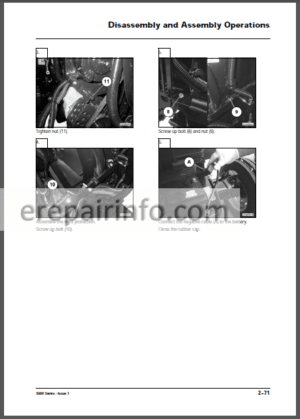
–ENGINE OUTPUT SHAFT
General
Removal (From Engine)
Disassembly
Assembly
Installation
–COOLING SYSTEM
Radiator
Removal
Installation
Filling the Radiator
Charge Air Cooler
Removal
Installation
–CONDENSER / COOLER ASSEMBLY
Removal
Installation
–FUEL TANK
Removal
Installation
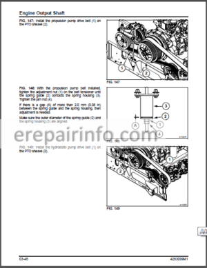
–ENGINE DRIVES
Propulsion Pump Drive
Belt Removal
Belt Installation
Propulsion pump Drive Sheave Removal
Propulsion Pump Drive Sheave Installation
Hydrostatic Pump Drive
Belt Removal
Belt Installation
Tandem Pump Drive Sheave Removal
Tandem Pump Drive Sheave Installation - – MATERIAL HANDLING
FEEDER HOUSING
General Information
Header Fixed Speed Countershaft Drive Belt
Removal
Installation
Drive Belt Idler SheaveHeader Fixed Speed Countershaft
Removal
Installation
Header Variable Speed Countershaft Drive Belt And Flat Idler
Removal
Installation
Jackshaft Drive Belt
Removal
Installation
Jackshaft Drive Belt Idler Sheave
General Information
Removal
Installation
Pivot Shaft Drive Belt
General Information
Removal
Installation
Pivot Shaft Drive Belt Idler Sheave
General Information
Removal
Installation
Feeder Conveyor Chain Slats
General Information
Removal
Installation
Feeder Conveyor Chain
General Information
Adding and Removing Chain Links
Adjustment
Check Feeder Chain Wear
Removal
Installation
Adjusting Position BlocksFeeder Drum Float
Front Feeder Drum And Shaft
Removal
Installation
Countershaft Variable Speed Header Drive
Removal
Disassembly
Inspection of Parts
Assembly
Installation
Countershaft Fixed Speed Header Drive
Removal
Installation
Feeder Housing Floors
Removal
Disassembly
Assembly
Installation
Seal
General Information
Removal
Installation
Feed Plate
Removal
Installation
Variable Speed Header Drive Jackshaft
General Information
Removal
Installation
Fixed Speed Header Drive Jackshaft
General Information
Removal
Installation
Feeder Housing
General Information
Removal
Installation
Lateral Tilt Assembly
General Information
Hydraulics
Electrical
Removal
Disassembly
Assembly
Installation
Pivot Shaft Slip Clutch
Removal
Disassembly
Assembly
Installation
Pivot Shaft
Removal
Installation
–CLEAN GRAIN SYSTEM
General Information
Clean Grain Elevator Drive Belt
Drive Belt Adjustment
Drive Belt Removal
Installation
Clean Grain Drive Belt Idler Sheaves
General Information
Idler Sheave Removal
Idler Sheave Installation
Clean Grain Elevator Conveyor Chain
Conveyor Chain Adjustment
Conveyor Chain Paddle Replacement
Conveyor Chain Removal
Installation
Clean Grain Cross Auger
Removal
Installation
Clean Grain Elevator
Removal
Installation
Grain Bin Loader
General Information
Grain Bin Loader Drive Chain
Upper Elevator Shaft
Bin Loader Auger Assembly
Bin Loader Drive Shaft
–RETURN GRAIN SYSTEM
General Information
Return Elevator Drive Belt
Drive Belt Adjustment
Removal
Installation
Drive Belt Idler Sheaves
Removal
Installation
Return Elevator Conveyor Chain
Conveyor Chain Adjustment
Conveyor Chain Paddle Replacement
Conveyor Chain Removal
Conveyor Chain Installation
Return Grain Cross Auger
Removal
Installation
Return Grain Elevator
Removal
Installation
Upper Elevator Shaft
Removal
Installation
Upper Return Auger
Removal
Installation
Upper Head Assembly
Removal
Installation
Return Grain Torque Limiter
Disassembly
Assembly
–UNLOADING AUGER SYSTEM
General Information
Unloader Auger System Shear Bolts
Angled Auger
Cross Auger
Unloader Drive Belt
Unloader Drive Adjustment
Drive Belt Removal
Drive Belt Installation
Drive Belt Idler SheavesUnloading Auger System
General Information
Removal
Installation
Unloader Jackshaft
Removal
Installation
Main Cross Auger
Removal
Disassembly
Assembly
Installation
Righthand U-Joint And Bearing Assembly
Removal
Disassembly
Assembly
Installation
Angled Unloader Auger
Removal
Disassembly
Assembly
Installation
Unloading Auger Tube
Removal
Installation
Unloading Auger Coupler And Pilot Ring
Removal
Installation
Unloading Auger Spill Reducer Assembly
Removal And Disassembly
Assembly And Installation
Unloading Auger Outer Bearing
Removal
Installation
Unloading Auger
Removal
Installation
–UNIVERSAL JOINT REPLACEMENT
Disassembly
Assembly
–POWER FOLD GRAIN TANK EXTENSIONS
Power Fold Grain Tank Extension Switch
Entering The Grain Tank
Grain Tank Seals
Push Rods And Rocker
Actuators
Removal
Installation - – MATERIAL DISCHARGE
–STRAW CHOPPER
General Information
Adjustments
Spread Width
Chopper Support Rails
Knife Replacement
Straw Chopper Secondary Drive Belt
Drive Belt Adjustment
Drive Speeds
Removal
Installation
Drive Belt Idler SheavesSecondary Drive
Removal
Installation
Straw Chopper Primary Drive Belt
Drive Belt Adjustment
Removal
Installation
Drive Belt Idler SheavePrimary Drive
Removal
Installation
Jackshaft
Removal
Disassembly
Assembly
Installation
Straw Chopper
Removal
Disassembly
Assembly
Installation
–CE STRAW CHOPPER
General Information
Windrow Converger
Fine Cut Knife
Adjustments
Fine Cut Knife
Spreader Board
Spreader Fins
Straw Chopper Knives
Knife Replacement
Straw Chopper Drive
Sheave Removal and Installation
Primary Drive Adjustment
Primary Drive Belt Replacement
Primary Drive Idler Arm and Sheave
Secondary Drive Adjustment
Secondary Drive Belt Replacement
Secondary Drive Idler Arm and Sheaves
Jackshaft
Straw Chopper
Removal
Disassembly
Assembly
Installation
–STRAW SPREADER
General Information
Straw Spreader Primary Drive
Adjustments
Drive Belt Replacement
Idler Arm and Sheave
Straw Spreader Secondary Drive
Adjustments
Drive Belt
Idler Arm and Sheave
Jackshaft
Removal
Disassembly
Assembly
Installation
Straw Spreader
Removal
Disassembly
Assembly
Installation
–CHAFF SPREADER
General Information
Adjustments
Positioning The Chaff Spreader
Adjustment Of Disc Speed
Removal
Disassembly
Assembly
Installation - -REAR AXLE
–STANDARD REAR AXLE
Adjustable Steering Axle – Standard
General Information
Standard Rear Axle Wheel Bolt Torque
Steering Cylinder Removal
Steering Cylinder Installation
Bleeding Steering Cylinder and Lines
Adjusting Rear Axle Wheel Tread Width
Adjusting Rear Wheel Toe-In
Axle Removal
Axle Installation
Rear Wheel Bearing Removal And Disassembly
Cleaning, Inspection, And Installation
Spindle Bushing Removal
Spindle Bushing Installation
Steering Stop Adjustment
Adjustable Steering Axle – If Equipped
General Information
Rear Wheel bolt Torque
Adjusting Rear Axle Wheel Tread (Width)
Adjusting Rear Wheel Toe-in
Axle Stop Adjustment
Rear Wheel Bearing Lubrication and Adjustment
Axle Removal and Disassembly
Axle Assembly and Installation
–POWER REAR AXLE
Power Rear Axle – Single Speed
General Information
Power Rear Axle Identification
Power Rear Axle Wheel Motor Identification
Power Rear Axle Performance
Power Rear Axle Electrical Components And Controls
Power Rear Axle Hydrostatic Circuits Description
Case Drain Return 0 to 2758 kPa (0 to 40 psi)
Power Rear Axle Operation Description
Steering Cylinder Operation
Steering Cylinder Removal
Steering Cylinder Installation
Bleeding Steering Cylinder and Lines
Rear Wheel Lug Nut Torque
Rear Wheel Motor Axle Bearings
Wheel Motor Steering Pin Bushings
Adjusting Rear Axle Wheel Tread Width
Adjusting Rear Wheel ToeIn
Checking And Tightening Rear Wheel Tie Rod Ends
Wheel Stop Adjustment
Axle Removal
Axle Installation
Power Rear Axle EquaTrac Ii Valve Components
Operation Of EquaTrac Ii Valve
Power Rear Axle Wheel Motor
Basic Motor Repair
Power Rear Axle Service Tools
Power Rear Axle Troubleshooting And Testing
Power Rear AxleTwo Speed
General Information
Power Rear Axle Identification
Power Rear Axle Wheel Motor Identification
Basic Motor Specifications
Power Rear Axle Performance
Power Rear Axle Electrical Components And Controls
Hydrostatic Circuitry Description
Case Drain Return
Operation Description
Rear Wheel Lug Bolt Torque
Rear Wheel Motor Axle Bearings
Wheel Motor Steering Pin Bushings
Adjusting Rear Axle Height
Wheel Motor CFrame Mounting Bolts
Adjusting Rear Axle Wheel Tread (Width)
Adjusting Rear Wheel ToeIn
Checking And Tightening Rear Wheel Tie Rod Ends
Wheel Stop Adjustment
Axle Removal
Axle Installation
Selector Valve
Selector Valve Principle Of Operation
Power Rear Axle Wheel Motor
Principle Of Operation (For The Route Of One Piston)
Removal
Steering CFrame Removal And Installation
Disassemble And Assemble Bushings
Installation
Wheel Motor Bleeding/StartUp Procedures
Bleeding And StartUp Procedures
Power Rear Axle Service Tools
Basic Motor Repair
Troubleshooting And Testing - – THRESHING AND SEPARATING
–BEATER
General Information
Drive Belt
Removal
Installation
Beater Drive Belt Idler Sheaves
Removal and Disassembly
Assembly and Installation
Beater and Shaft
Removal
Installation
Bearing Replacement
Lefthand Bearing
Righthand Bearing
Header Drive Clutch Assembly
Removal and Disassembly
Assembly and Installation
–STONE TRAP
General Information
Handle
Removal
Installation
Stone Trap Cover Plate (Accessory)
ROTOR
General
Cylinder Bars
Removal
Installation
Rotor Assembly
Removal
Installation
Front Stub Shaft
Removal
Installation
Front Bearing
Removal
Installation
Rear Drive Hub
Removal
Installation
Rotor Inlet Flighting
Removal
Repair
Installation
Knives
Removal
Installation
Sweeps (Paddles)
Discharge Sweeps
Separator Sweeps
Rotor Repair
Skin Dents
Static Balancing
ROTOR GEARBOX
General Information
Rotor Drive
Lubrication
Rotor Gearbox Shift Lever
Removal
Disassembly
Inspection
Assembly
Installation
–CONCAVES
General Information
Adjustment
Calibrations
Removal
Installation
Concave Adjustments
Concave Alignment
Leveling and Indexing Concave
Concave Overlaps
Solid
Perforated
Concave Blanks
–SEPARATOR GRATES
General Information
Removal
Installation
–ROTOR GUIDE VANES / GUIDE VANE SHELL
Rotor Guide Vanes
Removal
Installation
Rotor Guide Vane Shell
Removal
Installation
–SEPARATOR RETURN PAN
General Information
Rear Separator Pan Seal
Removal
Installation
Separator Return Pan Side Frame Seals
Removal
Installation
Separator Return Pan Support Bearings
Removal
Installation
Rear Support Shaft Bearings
Removal
Installation
Front Support Shaft Bearings
Removal
Installation
Separator Return Pan
Removal
Installation
–CHAFFER / CLEANING SHOE / SHAKER SHAFT
General Information
Cleaning (Shaker) Shoe
Adjustable Chaffer (Upper Cleaning Screen)
Fixed Air Foil Chaffer (Upper Cleaning Screen)
Adjustable Sieve (Lower Cleaning Screen)
Chaffer (Top Screen)
Removal
Installation
Sieve (Lower Screen)
Removal
Installation
Cleaning Shoe Frame Assembly
Removal
Installation
Cleaning Shoe Frame Front Support Bearing
Removal
Installation
Cleaning Shoe Frame Hanger Arm BearingsUpper
Removal
Installation
Cleaning Shoe Frame Rear Support Shaft Bearing
Removal
Installation
Cleaning Shoe Frame Front Sea-lUpper
Removal
Installation
Cleaning Shoe Frame Front Seal-Lower
Removal
Installation
Cleaning Shoe Side Frame Seals
Removal
Installation
Cleaning Shoe Corner Seals
Removal
Installation
Lower Separator Pan
Removal
Installation
Lower Separator Pan Front Support Bearings
Removal
Installation
Lower Separator Pan Rear Support Shaft Bearings-Upper
Removal
Installation
Lower Separator Pan Rear Support Shaft Bearings-Lower
Removal
Installation
Lower Separator Pan Side Frame Seals
Removal
Installation
Shaker Shaft
Removal
Installation
Shaker Shaft Righthand Support Bearing
Removal
Installation
Shaker Shaft LeftHand Support Bearing
Removal
Installation
CLEANING SHOE PITMAN
Drive Belt
Removal
Installation
Drive Belt Tensioning Idler
Disassembly
Assembly
Idler Sheave Alignment
Pitman Shaft
Removal and Disassembly
Assembly and Installation
CLEANING FAN
General Information
Fan Speed Adjustment
Fan Speed Ranges
Cleaning Fan Accessory
Drive Belt
Removal
Installation
Variable Speed Driven Sheave
Removal
Installation
RightHand Bearing
Removal
Installation
LeftHand Bearing
Removal
Installation
Fan Assembly
Removal
Disassembly
Assembly
Balancing
Installation
–THRESHER DRIVE MAIN COUNTERSHAFT
General Information
Drive Belts
Removal
Installation
Drive Belt Idler
Removal And Disassembly
Assembly And Installation
Alignment And Adjustment
Main Countershaft
Removal And Disassembly
Assembly And Installation - – FRONT AXLE
–BRAKES
General Information
Brakes
Basic Operating Principles
Drum Brakes
Brake Inspections
Brake Lines and Hoses
Master Cylinder Operation
Checking Brake Fluid Level
Master Cylinder
Removal
Disassembly
Inspection and Cleaning
Assembly
Bench Bleeding Master Cylinder
Installation and Adjustment
Brake Wheel Cylinder
Removal
Installation
Disassembly And Assembly Of The Wheel Cylinder
Replacing The Shoe And Lining Assemblies
Removal Of Brake Drums
Removal Of Brake Assembly
Removal Of Shoe And Lining Assemblies
Removal Of Brake Parking Lever
Cleaning And Inspection Of Parts
Installation Of Adjuster Cable
Parking Brake Assembly
Installation Of Shoes To Backing Plate
Installation Of Brake Assembly
Installation Of Brake Drum
Brake Shoe To Drum Adjustment
Used Or New Brake Drums
New Brake Drums
In Combine
Parking Brake Adjustments
Minor Adjustment
Major Adjustment
Parking Brake Adjustment Procedure
Bleeding Brake System
Manual Bleeding
–FINAL DRIVE
General Information
Identification
Final Drive Capscrew Torques
Removal
Disassembly
Assembly
Installation
Oil Level
Final Drive Riser
General Information
Installation
–TRANSMISSION
General Information
Transmission Identification
Combine Transmission Capscrew Torque
Transmission Maintenance
Transmission Lubrication Pump
General Information
Testing
Replacement
Transmission
Removal
Installation
Transmission Shifter
Transmission Shifter Assembly Adjustment
Transmission Shifter Cable Adjustment
Transmission Shifter Assembly
Shift Rails, Forks, and Top Cover
Bearing Adjustment Procedures
All Shafts And Differential
Differential
Removal
Output Shaft and Differential Carrier
Differential Assembly
Installation
Input Shaft
Seal Replacement With The Transmission Installed
Input Shaft Removal
Input Shaft Installation
Main Pinion Shaft
Removal
Installation
Countershaft
Countershaft Removal
Countershaft Installation
Transmission Troubleshooting
Transmission Troubleshooting Table - -HYDRAULICS
–GENERAL INFORMATION
General Information
Hydraulic Schematic (Pressure And Flow Compensated Load Sense System)
Axial Piston Pump (Load Sense Compensator)
Filter Screen
Oil Filters
Priority And Shuttle Valve
MonoBlock Main Control Valve
Lateral Tilt Valve
Hydraulic Load Sensing System
During Low Pressure Standby Mode (No Steering Demand)
During Activation Of Load Sense (Pressure And Flow Compensated) Functions
During High Pressure Standby Mode (Flow Compensated Functions)
–HYDRAULIC RESERVOIR
General
Draining
Removal
Cleaning The Strainer Assembly
Removal
Screen Cleaning
Installation
Disassemble And Clean The Hydraulic Reservoir
Installation
RESERVOIR STRAINER SCREEN HYDRAULIC
Removal
Screen Cleaning
Installation
–OIL FILTER
General
Removal
Installation
–HYDRAULIC CONTROL VALVE
General
Hydraulic Control Valve
Valve Locations
Main Control Valve Port Location
Hydraulic Lines
Valve Adjustments
Hydraulic Valves
O-Rings And Backup Rings
Unloader Swing In And Out Valve
Reel Fore And Aft Valve (Optional)
Feeder Reverser Valve
Chaff Spreader, Reel Lift Lower, And Master Valve
Reel Lift Raise Valve
Reel Speed Valve And Header Lift / Lower
Reel Speed Pressure Compensator
Chaff Spreader / Rotary Screen Pressure Compensated Flow Regulator
Load Sense Pressure Regulator
Auger Swing Check Valves
Reel Fore And Aft Check Valves (Option)
Chaff Spreader, Rotary Screen, Header Lift, Load Sense, And Reel Speed Check Valves
Header Lift And Feed Reverser Check Valves
Unloader Swing Fast Valve
Troubleshooting
Main Control Valve Assembly
Chaff Spreader Valve
Rotary Screen Valve
Reel/Pickup Speed Valve
Header Lift
Auger Swing
Feed Reverser
Reel Lift
Reel Fore And Aft (Ce)
Solenoid Troubleshooting
Solenoid Torque Values
Removal And Installation Of Hydraulic Control Valve
Removal
Installation
–LATERAL TILT VALVE
General
ORings And Backup Rings
Removal
Disassembly
Inspection
Assembly
Installation
Troubleshooting
Solenoid Troubleshooting (Directional Control Valve Solenoids)
Solenoid Troubleshooting (Float Solenoid Valves)
Lateral Tilt Valve Assembly
–PRIORITY VALVE
General
Operating Modes
Normal Operation (No Steering Demand)
Steering Demand Mode
Steering Relief Mode
Priority Valve Troubleshooting
Priority Valve Disassembly And Assembly
Disassembly
Assembly
–UNLOADER ENGAGE AND ROTOR DISCONNECT VALVE
General
Operating Modes
Disengaged
Engaged
Troubleshooting
Disassembly
Inspection
Assembly
–SHUTTLE VALVE
General
Removal
Installation
–VARIABLE SPEED RELIEF VALVE
General Information
Testing The Relief Valve On The Combine
Testing The Relief Valve Off The Machine
Servicing the Relief Valve
OIL COOLER BYPASS VALVE
General Information
Servicing of Oil Cooler Bypass Valve
Testing
–CHAFF SPREADER FLOW DIVIDER
General Information
Flow Divider Cartridge
ORings And Backup Rings
Removal
Disassembly And Inspection
Assembly
Installation
Troubleshooting
Chaff Spreader Flow Divider
–SINGLE POINT FIXED CONNECTOR
General Information
Single Point Fixed Connector
Single Point Mobile Connector (Header)
Connecting the Single Point Couplers
Cartridge Removal and Installation
Fixed Plate (Machine)
Removal
Disassembly
Assembly
Installation
Single Point Mobile Connector (Header)
Removal
Disassembly
Assembly
Installation
–HEADER LIFT CYLINDERS
General
Removal
Disassembly
Inspection
Reassembly
Installation
–REEL LIFT CYLINDERS
Reel Lift Master Cylinder
Removal From Header
Installation On Header
Disassembly
Inspection
Reassembly
Reel Lift Slave Cylinder
Removal From Header
Installation On Header
Disassembly
Inspection
Reassembly
–UNLOADING AUGER TUBE SWING CYLINDER
General
Operation
Extend (Out)
Retract (In)
Removal
Disassembly
Inspection
Reassembly
Installation
Bleeding Unloading Auger Tube Swing Cylinder and Lines
–STEERING CYLINDERS
Standard Rear Axle
General
Operation
Removal
Disassembly
Inspection
Reassembly
Installation
RWA Rear Axle (Class 6 and 7)
General
Operation
Removal
Disassembly
Inspection
Reassembly
Installation
Bleeding Steering Cylinders and Lines (One Double Acting)
RWA Rear Axle (Class 8 On Class 7)
General
Removal
Disassembly
Inspection
Reassembly
Installation
Bleeding Steering Cylinders and Lines (Two Double Acting)
–UNLOADING AUGER ENGAGE CYLINDER
General
Operation
Removal
Disassembly
Inspection
Reassembly
Installation
Bleeding Unloader Engage Cylinder and Line
–HEADER LATERAL TILT CYLINDER
General
Disassembly
Inspection
Reassembly
–HYDRAULIC ACCUMULATOR
General
Special Tools
To Lock Out The Accumulator
Removal
Installation
Discharging The Accumulator
Charging The Accumulator
To Check The Charge At Any Time
Accumulator Disassembly
Inspection
Accumulator Assembly
–HYDROSTATIC DRIVE SYSTEMS
General
Model A66, 660B And 9695
Models A76, 670B And 9795
Rotor And Propel Pump Hydraulic Schematic
Principle Of Operation Of A Hydrostatic Motor
Principle Of Operation Of A Hydrostatic Pump
Operation
Neutral Position
Stroked (Forward) Position
Stroked (Reverse) Position
Multi-Function Valve
System Check Valve
Pressure Limiter Operation
High-Pressure Relief Operation
–PRIMING, FLUSHING, CLEANING, AND START-UP OF HYDRAULIC SYSTEM
General
Class 6
Class 7
Priming The Suction Line For The Main Hydraulic Pump
Priming The Hydrostatic Charge Pump Suction Filters And Lines
Suction Filters
CHarge Pump Suction Lines
Flushing And Cleaning
Hydraulic System Start-Up Procedures
After Servicing Of The Suction Lines, Suction Screen, Or Suction Filter(S)
Starting-Up A New/Repaired Hydraulic Pump
Hydrostatic Propulsion Drive Start-Up Procedures (New/Repaired Pump/Motor)
Hydrostatic Rotor Drive Start-Up Procedures (New/Repaired Pump/Motor)
–HYDROSTATIC ROTOR DRIVE SYSTEM
General
Rotor Drive Motor
Removal
Installation (Models A66, 660B and 9695)
Installation (Models A76, 670B and 9795)
Rotor Pump (Models A66, 660B and 9695)
Removal
Disassembly
Reassembly
Installation
Rotor Drive Tandem Pump (Models A76, 670B and 9795)
Removal
Disassembly
Reassembly
Installation
Hydrostatic Rotor Drive System Adjustments
Electric Displacement Control (Edc) And Hydraulic Displacement Control (Hdc) Neutral Adjustment
Multi-Function Valve Adjustment (Pressure Limit & High Pressure Relief Valve)
Pump Charge Pressure Relief Valve Adjustment
Motor Charge Pressure Relief Valve Non-Adjustable (Forward)
Hydrostatic Rotor Drive System – Test Port Locations
Hydrostatic Rotor Drive Troubleshooting Tables
Neutral – Difficult or Impossible to Find
System Operating Hot
Transmission Operates Normally in One Direction Only
System Will Not Operate in Either Direction
Low Motor Output Torque
Improper Motor Output Speed
Excessive Noise and/or Vibration
System Response is Sluggish
Hydrostatic Rotor Drive Electronic Speed Control Module/Reversing Switch
Thresher (Rotor) Engage Switch
Rotor Speed (Control Console)
HYDROSTATIC PROPULSION DRIVE SYSTEM
General Information
Pump
Motor
Transmission Components
Manual Displacement Control (MDC)
Multi-Function Valve (Pressure Limiter and High Pressure Relief)
Pressure Limiter Operation
High-Pressure Relief Operation
Motor Operation
Hydrostatic Propulsion Motor
Removal
Installation
Propel Pump (Models A66, 660B and 9695)
Removal
Disassembly
Reassembly
Installation
Propel Pump (Models A76, 670B and 9795)
Removal
Installation
Hydrostatic Propulsion Drive System Adjustments
Multi-Function Valve Adjustment (Pressure Limiter and High Pressure Relief Valve)
Pump Charge Pressure Relief Valve Adjustment
Motor (Forward/Reverse) Charge Pressure Relief Valve Non-Adjustable
Hydrostatic Propulsion Drive Troubleshooting Tables
Neutral – Difficult or Impossible to Find
System Operating Hot
Transmission Operates Normally in One Direction Only
System Will Not Operate in Either Direction
Low Motor Output Torque
Improper Motor Output Speed
Excessive Noise and/or Vibration
System Response is Sluggish
Test Port Locations
Series 90 Pump
Series 90 Motor
HYDROSTATIC PUMP AND MOTOR REPAIR
General
Series 90 Pump (Rotor and Propulsion Drive)
Input Shaft Seal
Multi-Function Valve Cartridges (High Pressure Relief Valves)
Charge Pressure Relief Valve
Charge Pump
Auxiliary Pad Installation
Displacement Control Valve (Propel Pump)
Pressure Control Pilot Valve (PCP) (Rotor Pump Only)
Disassembly
Clutch Disassembly
Clutch Assembly
Motor Disassembly
Inspection Of Gerotor Motor Components
Motor Assembly Procedure
Assembly Of Gerotor Hydraulic Motor
Assembly Of Clutch Housing To Gerotor Hydraulic Motor
–HYDRAULIC CHAFF SPREADER MOTOR
General Information
Hydraulic Chaff Spread Motor Components
Removal
Disassembly
Inspection
Installation
–HYDRAULIC ROTARY SCREEN DRIVE
General
Hydraulic Schematic
Adjustment of Flow Control
Removal and Disassembly
Inspect Parts For Wear
Assembly and Installation
Placing System Back Into Service
Troubleshooting Drive System
–ROTOR DISCONNECT CYLINDER (CLASS 7)
Operation
Removal
Disassembly
Assembly
Installation - -ELECTRICAL
–GENERAL INFORMATION
Introduction
Basic Troubleshooting Procedures
Tools
General Testing Procedures
Visual Inspection
Continuity Check
Voltage Check
Testing For Open Circuits
Finding An Open Circuit
Testing For Short Circuits
Testing For High Resistance
–CONSOLE II TERMINAL
Console Ii Terminal
Gauges
Work Screen
Unloading Auger
Header Position
Percentage Of Header Used
Digital And Analog Display
Header Screen
Reel Control
Header Control
Combine Screen
Engine Screen
Miscellaneous Screen
Setup
System Setup
Maintenance
Calibrations
Vmm Diagnostics
Mvec Diagnostics
Engine Alarms
Alarms
Software Version
Symbols And Alarms
1St Message And Alarm Area
2Nd Message And Alarm Area
3Rd Message And Alarm Area
4Th Message And Alarm Area
5Th Message And Alarm Area
6Th Message And Alarm Area
7Th Message And Alarm Area
8Th Message And Alarm Area
Engine Diagnostics
Engine Trouble Code List
–CAB ELECTRICAL COMPONENT LOCATIONS
Electronic Modules
Steering Column
Seat and Console
Right-hand Seat Mounted Console
Right-hand Armrest Switches
Seat
Park Brake
Overhead Console
Lights and Wiper Switches
Heating and Air Conditioning
Electric Mirrors (Optional)
Windshield Wiper
Radio
Power Outlets
CHASSIS SENSOR LOCATION
Adjusting Switches
Adjusting Inductive Sensors
Sensors, Switches, Electrical Components
Miscellaneous Electrical Components
ELECTRICAL CIRCUITS
Fuse and Relay Panel
Relay Locations
Fuse Location and Amperage
Fuses and Relays Outside of Cab
Primary Circuit Breaker
MVEC Relay Boxes
Location
Relay/Fuse Location
VMM Inputs/Outputs
VMM1
VMM2
VMM3
VMM4
VMM5
VMM6
Testing
Fuse Testing
Relay Testing
Diode Test
Machine Grounds
Cab Frame Grounds
Under Cab Grounds
Main Machine and Battery Grounds
–WIRING DIAGRAMS
General Information
Harness Abbreviations
Splice Cross Reference
Wiring Diagrams
Air Conditioner and Blower
AutoGuide
Beacon Light
Clutch and Feeder Reverse
Concave and Separator Fan Control
Grain Loss Monitor
(HUC6101 to HUC6999)
Grain Loss Monitor(Huc7101 To Huc7999)
Lighter And Power Receptacles
Power Ladder
Rear Work And Service Lights
Rotor Speed Control
Sieve And Chaffer Control
Switch Circuits
Unloading Auger And Swing
Windshield Wiper, Seat Switch, And Power Mirrors
Header Height And Tilt
Rear Wheel Assist
Reel Position And Reel Speed
Headlights
Switch Backlighting
Steering Column
Radio And Horn
Power Distribution
Engine Start/Run
Fieldstar And Moisture Sensor
Sensor Circuits
Speed Sensors
Grain Bin Switch Circuits
Taillights, Backup Lights, And Alarm
Unloader, Exit, And Row Finder Lights
Field Lights
Data Bus And Auto Guide Roof
Smv And Turn Signals
Vertical Knife
ELECTRICAL TROUBLESHOOTING
Thresher, Header and Unloading Electromagnetic Clutch
General
Seat Interlock Switch
Electrical Header and Separator Clutch Troubleshooting
Ignition Key Turned to ON Position and Header and Thresher Switches Toggled ON
Clutch Removal and Installation
Clutch Magnet and Armature Inspection
Testing Clutch Magnet
Clutch Brush holder
Continuity Test
Diode Test
Brush Holder Servicing
Brush holder Installation
Bin Unloading Clutch Circuit
Troubleshooting
–BATTERIES
Safety Precautions
General
Battery Connections
Battery Disconnect Switch
Battery Connections
Starting Engine With Booster Battery
–STARTING SYSTEM
General Information
Ignition Switch
System Operation
Battery Condition
–CHARGING SYSTEM
Introduction
Operating Principles
Trouble Shooting
Charging Systems
Systems With Voltmeter
No output
Alternator Bench Test - -ELECTRONICS
–GENERAL INFORMATION
General
Electrical System
Batteries
Cleaning
–INPUTS AND OUTPUTS
Inputs and Outputs
Console
Combine Cab
Combine Speed Inputs
Control Handle Inputs
Righthand Console Switches
Wiring Diagram
Operating Specifications
Seat Interlock Switch
Thresher and Header Switch
Exit Light
Flasher/Hazard Lights
–ROTOR SPEED CONTROL
General Information
General
Rotor Speed Control / Reversing Switch
Operator Interface
Thresher On Mode
Thresher Off (Unplug) Mode
Electrical Circuit
Test Procedure
–CONSOLE CONTROLS
Reel Drive Electronic Speed Control
General
Calibration
Operating Specifications
Manual Mode
Automatic Mode
Automatic Header Height Control System
General Information
Manual Mode
Automatic Mode
Manual Override
AHHC Default (Manual) Mode
System Components
Header Height Control Operation
Automatic Header Height Control
Automatic Header Sensitivity and Height Control Adjustments
Return To Cut (RTC)
Float
Auto Header Tilt Control
General
Automatic Mode
Adjustments
Manual Mode
Standby
Calibration
Hydraulic System
Hydraulic Accumulator
Sensors
Sensor Operation
Sensor Setup
Flex Header Cutter Bar Linkage Adjustment
Ground Pressure
Cutterbar Angle
Sensor Linkage Settings
Header Diagnostic Fault Parameters
Fault Codes
Unloader Swing Automatic Mode
General
Manual Mode
Automatic Mode
Unloader Tube
System
Input Description
Output Description - – CAB AND HVAC
–REMOTE ELECTRIC ADJUST CAB MIRRORS
Components
Cab Mirror
Removal
Installation
–OPERATOR SEAT
Operator SeatEarly Production
General Information
Operation
Lubrication
Cushion Removal and Installation
Lumbar Support
Seat Back and Armrest
Seat Switch
Seat Angle and Seat Depth Adjuster
Seat and Slide Rails
Suspension Troubleshooting
Horizontal Shock Absorber
Vertical Shock Absorber
Vertical Shock Absorber Adjustment Cable
Compressor
Fore and Aft Isolation Unit
Height Control Component
Pneumatic Spring
Upper Part of the Suspension System
Lower Part of the Suspension System
Scissor Linkage
Operator SeatLate Production
Late Production
–STEERING COLUMN
General Information
Steering Column Adjustment
Turn Signal Switch
Ignition Switch
Steering Column Components
Steering Wheel
Removal
Installation
Steering Column
Removal
Disassembly
Assembly
Installation
–WINDSHIELD WIPER MOTOR
Windshield Wiper Motor
Removal
Installation
–HEADLINER
Front Headliner
Removal
Installation
Main Headliner
Removal
Installation
–CAB GLASS
Windshield
Installation
Rear Window
Installation
LeftHand Door Assembly
Components
Removal
Disassembly
Assembly
Installation
RightHand Door Assembly
Components
Removal
Disassembly
Assembly
Installation
–AIR CONDITIONING AND HEATING
Safety Precautions
Personal Injury Can Result if These Precautions Are Not Followed
Operation Information
System Operation
Efficient Operating Tips and Maintenance
Components and Operation of System
General Information
Pressure Temperature Relationship
Air Conditioning System Components
Compressor
System Protection Switches
Condenser
Receiver Drier
Thermal Expansion Valve
Evaporator
Blower Fan and Motor
Lines and Connections
Ra Refrigerant
Heat And Air Conditioning Controls
Compressor Refrigeration Oil
Check The Condition Of The Oil:
System Oil Level
Determining Oil Charge
Checking Oil Level
Compressor Mounting Angle (Degrees) Correct Dipstick Oil Level Units
Check the condition of the oil:
Service Tools
Manifold Gauge Set
Service Tools and Equipment
Moisture In A Refrigerant System
Single Drop Of Water
Moisture To Ice Crystals
Moisture To Acids
Increasing Acid Because Of Heat
Acid Results On Metals
Moisture Removal
Servicing Refrigeration System
Preliminary Checks
Drive Belt
Compressor Service Valves
Gauge Manifold Set
Fastening The Manifold Gauge Set
Leak Testing Procedure
Compressor Clutch Testing
Testing The System
Purging The Manifold Set (Hoses, Gauges, And Manifold)
Stabilizing The System
Performance Testing
Refrigerant Recovery (Discharging)
Evacuating The System
Charging The System
Diagnosis
Check The Easy Items First
Evaporator
Condenser
Compressor
Receiver Drier
Expansion Valve
Refrigerant Line Restrictions And Leaks
Electrical Checks
Troubleshooting Indicators
Procedure
False Compressor Seizure
Compressor And Fan Belt Test
Compressor Function Test
Expansion Valve Function Test
Troubleshooting Chart
System Fault Finding
Procedure
Pressure Reading Diagnosis
Procedure
Pressure Problem Chart
Test Condition 1
Test Condition 2
Test Condition 3
Test Condition 4
Test Condition 5
Test Condition 6
Test Condition 7
Test Condition 8
Test Condition 9
Test Condition 10
Test Condition 11
Test Condition 12
Air Conditioning Test Data Log Sheet:
Compressor Clutch
Electrical Check
Removal And Replacement
Disassembly
Pulley Bearing
Assembly
Air Conditioning Compressor
Contents
Removal
Installation
Service Valves
Lubrication
Evaporator And Condenser Core Repairs
Condenser
Removal
Installation
General
Evaporator And Expansion Valve
Removal
Installation
Receiver Drier
Removal
Installation
High And Low Pressure Switches
Replacement
Troubleshooting High Pressure Switch
Troubleshooting Low Pressure Switch
AntiIcing Temperature Sensor
Removal
Installation
Troubleshooting The AntiIcing Temperature Sensor
Internal Air Temperature Sensor
Troubleshooting The Internal Air Temperature Sensor
External Air Temperature Sensor
Troubleshooting The External Air Temperature Sensor
Mixed Air Temperature Sensor
Troubleshooting The Mixed Air Temperature Sensor
Blower Motor
Removal
Installation
Hose Replacement
Procedure
SpecificationsRefrigeration ORing Fitting Torque Chart
Cab Air Filter
Cab FilterPrimary
Cab FilterSecondary
Recirculation Filter
Cab Filters
Heater Core
Removal
Installation
Electronically Controlled Water Valve
Removal
Installation
Heating And Air Conditioning Controls
Removal
Installation
Troubleshooting Automatic Temperature Control
Sensor Malfunctions
Air Conditioning And Blower Relays
Control Panel Connectors
What you get
You will receive PDF file with high-quality manual on your email immediately after the payment.


Anonymous (verified owner) –
It was great thank you so much