


Factory Service Manual For Mustang All Wheel Steer Loader. Manual Contains Illustrations, Instructions, Diagrams For Step By Step Remove And Install, Assembly And Disassembly, Service, Inspection, Repair, Troubleshooting, Tune-Ups.
Format: PDF
Language: English
Pages: 208
Issued: december 2008
Searchable: Yes
Wiring Diagrams: Yes
Hydraulic Diagrams: Yes
Model
Mustang All Wheel Steer Loader
ML360
ML460
Contents
-OPERATION
Important Information About This Manual
Brief Description
Machine Overview
Serial Plates And Component Numbers
Safety Decals
Fire Extinguisher (Option)
Cab Overview
Instrument Panel, Multi-Functional Lever And Switch Panel: Overview
Indicators And Warning Lights: Overview
Oil And Fuel Pre-Heater (Option)
Jump-Starting The Engine
Backup Warning System (Option)
Manual Throttle (Option)
Low-Speed Control (Option)
Towing The Machine
-SPECIFICATIONS
Frame
Types and Models: overview
Engine
Power train
Axles
Brakes
Steering System
Work Hydraulics
Pilot Control
Loader Unit With Bucket — Model ML360
Loader Unit With Bucket — Model ML460
Loader Unit With Pallet Forks — Model ML360
Loader Unit With Pallet Forks — Model ML460
Alternator, Starter, Battery
Fuse Box
Main Fuse Box — Model ML360
Main Fuse Box — Model ML460
Overview Of Switching Relays
Tires For Wheel Loader — Model ML360
Tires For Wheel Loader — Model ML460
Weights
Noise Levels
Vibration
Hardware Torques
Dimensions — Model ML360
Dimensions — Model ML460
-MAINTENANCE
Introduction
Fluids And Lubricants
Index To Component Maintenance
Explanation Of Symbols On Maintenance Label
Maintenance Label
Maintenance Schedule
Maintenance Of The Fuel System
Replacing The Fuel Filter
Cleaning The Fuel Pump Screen Filter
Bleeding The Fuel System
Checking/Adding Engine Oil
Changing Engine Oil
Changing The Engine Oil Filter Cartridge
Engine And Hydraulics Cooling System
Cleaning The Oil Cooler
Hydraulic System
Checking Hydraulic Pressure Lines
Monitoring The Hydraulic Oil Return Filter
Hydraulic Oil Return Filter
Checking The Hydraulic Oil Level
Adding Hydraulic Oil
Changing The Hydraulic Oil
Rear Axle Transfer Gearbox Oil Levels
Front And Rear Axle Differential Oil Levels
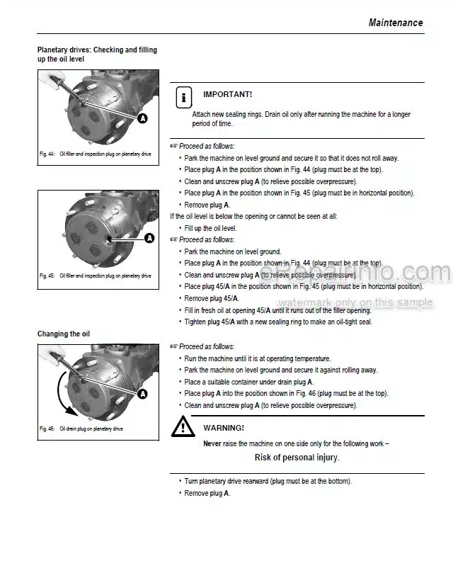
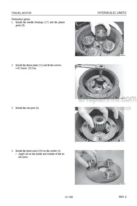
Front And Rear Axle Planetary Drive Oil Levels
Air Filter Maintenance
Replacing The Air Filter Cartridge
V-Belt
Lubrication Points
Lubricating The Loader Unit
Attachment Maintenance
Brake System
Tire Care
Changing Wheels
Heating
Electric System
Battery Maintenance
General Maintenance Work
Cleaning Inside The Cab
Cleaning The Seat Belt
Machine Exterior
Engine Compartment
Bolted Connections, Hinges
-ENGINE
F4M 2011/BF4M 2011 Engine: Overview
Engine Oil Cooling
Fuel System
Checking And Adjusting Valve Clearance
Replacing The Fuel Injection Pump
Setting The Charge-Air Pressure — Model ML460
Charge-Pressure Dependent Full-Load Stop — Model ML460
Turning Off Minus Compensation
Switching Off Minus Compensation — Model ML360
Heating Connection
Removing/Mounting The Cylinder Head
Sealing The Bleeder Valve
Engine Trouble
-POWER TRAIN
Variable-Displacement Pump Test Ports — Model ML360
Variable-Displacement Pump — Model ML360
Variable-Displacement Pump Test Ports, 12 mph (20 kph) — Model ML460
Variable-Displacement Pump, 12 mph (20 kph) — Model ML460
Variable-Displacement Motor, 12 mph (20 kph) — All Models
Variable-Displacement Pump Test
Inching Valve Overview
Inching Valve Circuit, 12 mph (20 kph)
Drive Circuit, 12 mph (20 kph) — Model ML360
Drive, 12 mph (20 kph): Wiring Diagram
Towing and Transporting the Machine
Test Report — Model ML360
Test Report — Model ML460
Power Train Adjustment
Adjusting Boost Pressure
Adjusting Starting Speed
Setting High Pressure/Drive Pressure
Setting The Secondary Valves For Forward/Reverse Driving
Setting The Pump Hydraulic Resistance (Characteristic Curve)
Setting Engine Droop
Setting Control Initiation On The Hydraulic Motor
Setting The Wheel Speed
-AXLES
Axle Overview
Sealing Service (Joint Housing/Axle Carrier)
Bevel Gear Shaft Seals
Differential Cage/Differential Lock Screw Connections
Overview Of Differential Lock And Differential Cage
Removing The Differential Cage With The Differential Lock
Removing The Differential Lock
Assembling The Differential Lock
Removing The Gearbox
Input Shaft Version 1 Sealing: Overview
Assembling The Gearbox
-BRAKES
Brake Circuit
Brake Diagram
Handbrake Circuit
Inching Valve Circuit, 12 mph (20 kph)
Service Brake
-STEERING
Steering Circuit For Model ML360
Steering Diagram For Model ML360
Steering Circuit For Model ML460
Steering Diagram For Model ML460
Steering System Adjustment
Hydraulic Ports On Servostat
Pressure Relief Valve: Adjustment
Steering Cylinder: Seals
Overview Of Steering Cylinder Adjustment
How To Adjust The Steering Cylinders
Checking The Track Setting
Correcting The Track Setting
Setting The Steering Limit
Checking Steering Synchronization
Setting Steering Synchronization
-HYDRAULIC SYSTEM
Test Report For Model ML360
Test Report For Model ML460
Work Hydraulics Oil Supply
Control Valve Ports
Priority Valve Ports
Priority Valve Diagram
Load Stabilizer Ports
Load Stabilizer Circuit
Load Stabilizer Diagram
Lift Cylinder: Seals
Tilt Cylinder: Seals
Control Cylinder (Quick-Hitch Frame): Seals
Work Hydraulics Diagram
-ELECTRICAL SYSTEM
Ohm’S Law
Measuring Equipment And Methods
Terminal Description
Cable Color Cooling
Relays
Starter, Battery, Alternator
Fuse Box
Main Fuse Box With Relays For Model ML360
Main Fuse Box With Relays For Model ML460
Switching Relays
Description Of Blocking Diodes
Overview Of Switch Assignment
Installing A Rotating Beacon
Installing The Backup Warning System
Installing Two Front Work Lights
Installing Two Front Work Lights And One Rear Work
Electric Diagram (Sheet 1) For Model ML360
Electric Diagram (Sheet 2) For Model ML360
Legend: Electric Diagram For Model ML460
Electric Diagram (Sheet 1) For Model ML460
Electric Diagram (Sheet 2) For Model ML460
What you get
You will receive PDF file with high-quality manual on your email immediately after the payment.


Reviews
There are no reviews yet.