


Factory Service Manual For Mustang All Wheel Steer Loader. Manual Contains Illustrations, Instructions, Diagrams For Step By Step Remove And Install, Assembly And Disassembly, Service, Inspection, Repair, Troubleshooting, Tune-Ups.
Format: PDF
Language: English
Pages: 216
Issued: june 2005
Bookmarks: Yes
Searchable: Yes
Wiring Diagrams: Yes
Hydraulic Diagrams: Yes
Model
Mustang All Wheel Steer Loader
ML68
Contents
-OPERATION
Important Information On This Service Manual
Serial Plates And Component Numbers
Machine Overview
Inside Of Cab: Overview
Inside Of Cab: Legend
Instrument Panel, Multifunctional Lever And Drive Lever: Overview
Instrument Panel, Multifunctional Lever And Drive Lever: Legend
-SPECIFICATIONS
Frame
Engine
Power Train
Axles
Brakes
Steering
Work Hydraulics
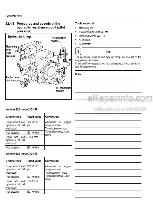
Pilot Control
Additional Control Circuit + High-Flow Control Circuit (Option)
Loader Unit
Electrical System
Tires
Weights
Sound Levels
Vibration
Hardware Torques
-MAINTENANCE
Fluids And Lubricants
Maintenance Decal
Maintenance Schedule Model ML68 (Overview)
Maintenance Items
Introduction
Fuel System
Engine Lubrication System
Engine And Hydraulics Cooling System
Air Filter
V-Belt
Gearboxes And Axles
Hydraulic System
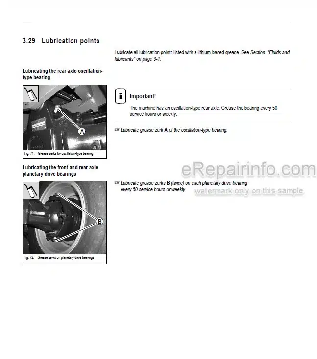
Lubrication Points
Attachments
Brake System
Tire Care
Changing Wheels
Electrical System
General Maintenance Work
Heating
-ENGINE
Engine BF4M 2011: Overview
Engine Oil Cooling
Fuel System
Checking And Adjusting Valve Tip Clearance
Replacing The Fuel Injection Pump
Setting Charge Air Pressure
Removing/Mounting The Cylinder Head
Engine Trouble
-POWER TRAIN
Variable Displacement Pump 12-25 mph (20 – 40 km/h)
Hydraulic Motor – Control Element 12 mph (20 km/h)
Hydraulic Motor – Hydraulic Connections 12 mph (20 km/h)
Powertrain Diagram 12 mph (20 km/h)
Eco-Speed – Hydraulic Motor 25 mph (40 km/h)
Eco Speed Power Train (25 mph [40 km/h]): Diagram
Test Report Model
Towing And Transporting The Machine
Check And Adjustment Instructions
Drive Electronics Operator’s Manual (SUSMIC)
Procedures (Sensor)
-AXLES
Serial Plate – Axle
Front Axle Screw Connections
Rear Axle Screw Connections
Drain, Fill And Check Plug – Front Axle
Drain, Fill And Check Plug – Rear Axle
Tightening Torques – Front Axle
Tightening Torques – Rear Axle
Sealing Work
-BRAKES
Brake Circuit
Service Brake
-STEERING
Steering Circuit
Steering Circuit
Hydraulic Ports On Servostat
Pressure Relief Valve – Servostat: Settings
Front/Rear Axle Steering Cylinder
Setting The Steering Sensors
-HYDRAULIC SYSTEM
Test Report
Control Valve Connections: Overview
Control Valve: Design
Pilot Control Unit: Design
Valve Block Connections: Overview
Pilot Control Circuit
Work Hydraulics Circuit
Load Stabilizer Circuit With Hose Burst Valve
Load Stabilizer: Circuit Diagram
Load Stabilizer With Hose Burst Valve: Circuit Diagram
Hose Burst Valve With Load Stabilizer: Connections
Hose Burst Valve Circuit
Hose Burst Valve Circuit
4Th Control Circuit (Front/Rear)
4Th Control Circuit (Front/Rear) Circuit
Lift Cylinder: Sealing Work
Tilt Cylinder: Sealing Work
Control Cylinder (Quickhitch Frame): Sealing Work
Work Hydraulics Diagram: Legend
Work Hydraulics Diagram
-ELECTRICAL SYSTEM
Ohm’s Law (Current, Voltage, Resistance Generates Power)
Measuring Equipment And Methods
Terminal Description
Cable Color-Coding
Relays
Electrical Units
Fuse Box On Left And Right Of Steering Column
Main Fuse Box With Relays
Relays
Steering Electronics
Instrument Panel, Fuse Box, Relays: Overview
Legend For Wiring Diagram
Wiring Diagram
Legend For Wiring Harness 207749: Engine – Frame
Wiring Harness: 207749: Engine – Frame
Legend For Wiring Harness 207750: Cab
Wiring Harness 207750: Cab
Wiring Harness 208562: Control Lever Base (Option)
Wiring Harness 207968: Control Lever Base (Standard)
Wiring Harness 207810: Steering-Column Control Lever
Wiring Harness 208111: Additional Control Circuit
Wiring Harness 208609 (Joystick)
Electronics Between Joystick And Wiring Harness 208609
Wiring Harness 207539: Rotating Beacon (Option)
Wiring Harness 207539: Front Working Light (Option)
Wiring Harness 208589: Load Stabilizer (Option)
Wiring Harness 208676: Solenoid Valve – Load Stabilizer (Option)
Wiring Harness 209185: Inching Sensor
Wiring Harness 209185: Crawler Gear – Potentiometer
Wiring Harness 208563: Number Plate Light (Option)
Wiring Harness 208113: Air-Suspension Operator’s Seat (Option)
Wiring Harness: Air Conditioning (Option)
Plug – SUSMIC
Relay Assignment
Plug And Socket Connection: Steering Electronics – Steering-Column Control Lever
Plug And Socket Connection: Fuse Box And Relay (Left)
Plug And Socket Connection: Fuse Box And Relay (Right)
Plug And Socket Connection: Cab
Plug And Socket Connection: Instrument Panel
Plug And Socket Connections: Load Stabilizer, Speedometer 25 mph (40 km/h), Front Socket
TORQUE SPECIFICATIONS
What you get
You will receive PDF file with high-quality manual on your email immediately after the payment.


Reviews
There are no reviews yet.